
Pin welding and drawing test device for PCB (Printed Circuit Board)

A pull-out test, PCB board technology, applied in the direction of measuring devices, using stable tension/pressure testing material strength, instruments, etc., can solve the problems of reduced efficiency, large time consumption, increased test process time, etc., to improve efficiency , simplified structure, and accurate test results

Active Publication Date: 2022-04-12
深圳市捷舜诚科技有限公司
View PDF10 Cites 0 Cited by
  • Summary
  • Abstract
  • Description
  • Claims
  • Application Information

AI Technical Summary

Problems solved by technology

[0002] After the pins are soldered on the PCB board, it is necessary to test the pull-out force of the pins. The traditional manual pull-out test method is labor-intensive and inefficient. After a long period of manual testing, workers are prone to fatigue. Pull-out test device, the working principle of these pull-out tests is to first position and fix the PCB board with a positioning device to keep it in a fixed state, and then use the pull-out device to clamp the pins and lock the pins before proceeding. Pulling, because the traditional pulling method is to pull vertically upwards, so the pulling test effect is not accurate. In actual use, the pin may bear the pulling force on the side, and the pulling force on the side has not been tested. Therefore, the strength of the pins is often not guaranteed when used later.
If you want to realize the side strength test of the pin, you must also set up a horizontal pull-out test structure, so for the pull-out test process, you also need to set up a horizontal and vertical pull-out structure, which makes the entire pull-out equipment very complicated. The test process time increases and the process increases
In addition, during the pull-out test, the positioning structure must be used to position the PCB board before the pull-out test. The entire positioning process takes a lot of time, and setting the positioning structure of the PCB will make the test device more complicated. After positioning and clamping, it is necessary to Disassemble the circuit board, the whole process is very troublesome, and the efficiency will be greatly reduced

Method used


Image

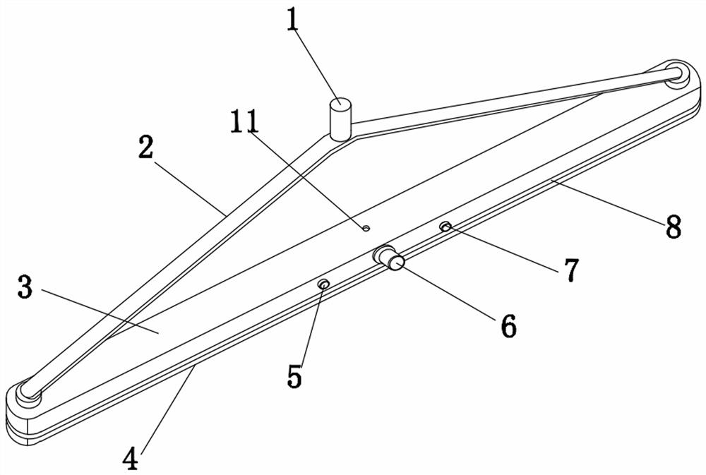
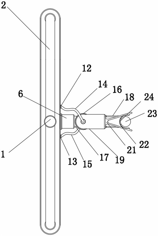
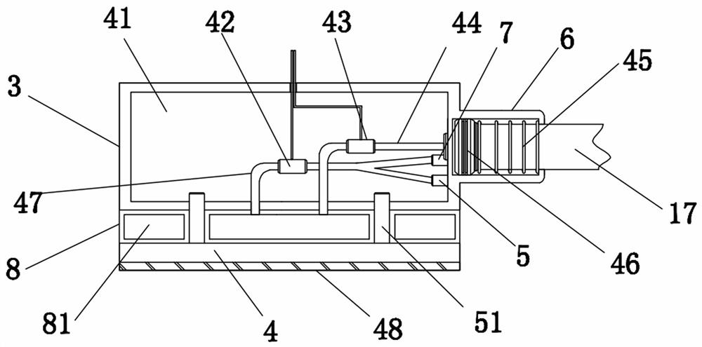
  • Pin welding and drawing test device for PCB (Printed Circuit Board)
  • Pin welding and drawing test device for PCB (Printed Circuit Board)
  • Pin welding and drawing test device for PCB (Printed Circuit Board)

Examples


Embodiment Construction

[0025] All features disclosed in this specification, or steps in all methods or processes disclosed, may be combined in any manner, except for mutually exclusive features and / or steps.

[0026] Any feature disclosed in this specification (including any appended claims, abstract and drawings), unless expressly stated otherwise, may be replaced by alternative features which are equivalent or serve a similar purpose. That is, unless expressly stated otherwise, each feature is one example only of a series of equivalent or similar features.

[0027] In describing the present invention, it is to be understood that the terms "one end", "the other end", "outer side", "upper", "inner side", "horizontal", "coaxial", "central", "end ", "length", "outer end" and other indicated orientations or positional relationships are based on the orientations or positional relationships shown in the drawings, which are only for the convenience of describing the present invention and simplifying the d...


PUM


Abstract

The invention discloses a PCB pin welding drawing test device which comprises a drawing test device installed at the bottom of a driving assembly, and the drawing test device is driven by the driving assembly to ascend and descend. The drawing test device comprises a contact plate, a shell and an elastic gas storage layer, the elastic gas storage layer is arranged between the contact plate and the shell, and after the drawing test device is driven by the driving assembly to press the PCB downwards, the contact plate is in contact with the upper end face of the PCB to be pressed tightly; a shaft sleeve is fixedly arranged on one side of the shell, a telescopic shaft is arranged in the shaft sleeve, and the inner side end of the shaft sleeve is connected with the elastic gas storage layer through a connecting pipe. According to the drawing test device, the welding strength of the side faces and the vertical direction of the pins of the PCB can be tested only by pressing the PCB downwards, integrated rapid and efficient testing can be achieved, the possible drawing environment of the PCB can be restored more truly in the testing process, the testing effect is more accurate, and the structural design is more reasonable.

Description

technical field [0001] The invention relates to the field of PCB board testing devices, in particular to a PCB board pin welding and pulling testing device. Background technique [0002] After the pins are soldered on the PCB board, it is necessary to test the pull-out force of the pins. The traditional manual pull-out test method is labor-intensive and inefficient. After a long period of manual testing, workers are prone to fatigue. Pull-out test device, the working principle of these pull-out tests is to first position and fix the PCB board with a positioning device to keep it in a fixed state, and then use the pull-out device to clamp the pins and lock the pins before proceeding. Pulling, because the traditional pulling method is to pull vertically upwards, so the pulling test effect is not accurate. In actual use, the pin may bear the pulling force on the side, and the pulling force on the side has not been tested. Therefore, the strength of the pins is often not guaran...

Claims


Application Information

Patent Timeline
IPC IPC(8): G01N3/14G01N3/02G01N3/04
Inventor 李存芝黄全国
Owner 深圳市捷舜诚科技有限公司
Features
  • Generate Ideas
  • Intellectual Property
  • Life Sciences
  • Materials
  • Tech Scout
  • Unparalleled Data Quality
  • Higher Quality Content
  • 60% Fewer Hallucinations
Learn More