Electric leakage detection circuit

A leakage detection and circuit technology, applied in the field of leakage detection, can solve the problems of small detection range and difficulty in detecting high-voltage leakage, and achieve the effects of simple structure, improved application scope, and reduced quantity

Pending Publication Date: 2022-04-12
JIANGSU WANBANG DEHE NEW ENERGY TECH CO LTD +1
View PDF0 Cites 0 Cited by
  • Summary
  • Abstract
  • Description
  • Claims
  • Application Information

AI Technical Summary

Problems solved by technology

[0002] The existing high-voltage leakage detection circuit for new energy generally uses the unbalanced bridge method or the pulse injection method, and these two solutions are usually used to detect the high-voltage positive or negative ground leakage, if the partial leakage between the positive and negative electrodes cannot be detected , In addition, due to the high-voltage resistance performance of high-voltage electronic components, it is difficult for the existing high-voltage leakage detection circuit to detect high-voltage leakage above 1000V, resulting in a small detection range

Method used


Image

  • Electric leakage detection circuit
  • Electric leakage detection circuit
  • Electric leakage detection circuit

Examples


Embodiment Construction

[0028]The following will clearly and completely describe the technical solutions in the embodiments of the present invention with reference to the accompanying drawings in the embodiments of the present invention. Obviously, the described embodiments are only some, not all, embodiments of the present invention. Based on the embodiments of the present invention, all other embodiments obtained by persons of ordinary skill in the art without making creative efforts belong to the protection scope of the present invention.

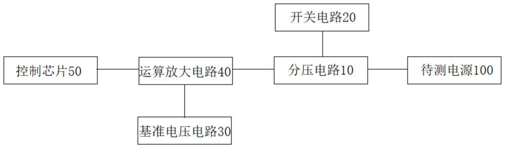
[0029] figure 1 It is a schematic block diagram of a leakage detection circuit according to an embodiment of the present invention.

[0030] like figure 1 As shown, the leakage detection circuit of the embodiment of the present invention includes a voltage divider circuit 10 , a switch circuit 20 , a reference voltage circuit 30 , an operational amplifier circuit 40 and a control chip 50 . Wherein, the voltage dividing circuit 10 is connected with the power s...


PUM


Abstract

The invention provides an electric leakage detection circuit comprising a voltage division circuit connected with a power supply to be detected; the switching circuit is arranged in the voltage division circuit and is used for controlling the on-off of the voltage division circuit; a reference voltage circuit; the operational amplifier circuit is respectively connected with the voltage division circuit and the reference voltage circuit and is used for generating electric leakage detection voltage when the voltage division circuit is switched on; and the control chip is connected with the switching circuit and the operational amplification circuit, electric leakage reference voltages of different positions of the power supply to be detected are arranged in the control chip, and when the voltage division circuit is switched on, the control chip judges whether the power supply to be detected leaks electricity according to the electric leakage reference voltages and the electric leakage detection voltages and judges the electric leakage position when the electric leakage occurs. High-voltage electric leakage detection can be realized, electric leakage detection between the positive electrode and the negative electrode of the to-be-detected power supply can be realized, the detection range can be expanded to ensure the safety of the to-be-detected power supply, and in addition, the structure is simple, and the cost is relatively low.

Description

technical field [0001] The invention relates to the technical field of electric leakage detection, in particular to an electric leakage detection circuit. Background technique [0002] The existing high-voltage leakage detection circuit for new energy generally uses the unbalanced bridge method or the pulse injection method, and these two solutions are usually used to detect the high-voltage positive or negative ground leakage, if the partial leakage between the positive and negative electrodes cannot be detected , In addition, due to the high-voltage resistance performance of high-voltage electronic components, it is difficult for the existing high-voltage leakage detection circuit to detect high-voltage leakage above 1000V, resulting in a small detection range. Contents of the invention [0003] In order to solve the above technical problems, the present invention provides a leakage detection circuit, which can realize high-voltage leakage detection, and can realize leak...

Claims


Application Information

Patent Timeline
IPC IPC(8): G01R31/52
Inventor 夏新辉蔡宪逸谢大权沈静张健梁冬
Owner JIANGSU WANBANG DEHE NEW ENERGY TECH CO LTD
Why Eureka
Try Eureka