Velocity defuzzification method and processing equipment for millimeter-wave radar under mimo system

A millimeter-wave radar, de-ambiguity technology, applied in radio wave measurement systems, radio wave reflection/re-radiation, instruments, etc., can solve the problem of unambiguous speed measurement range, etc., to expand practical value, solve speed ambiguity, and improve speed measurement range effect

Active Publication Date: 2022-06-17
GBA BRANCH OF AEROSPACE INFORMATION RES INST CHINESE ACAD OF SCI
View PDF9 Cites 0 Cited by
  • Summary
  • Abstract
  • Description
  • Claims
  • Application Information

AI Technical Summary

Problems solved by technology

[0004] The purpose of the present invention is to provide a millimeter-wave radar speed deambiguation method and processing equipment under the MIMO system, so as to solve the technical problem of low unambiguous speed measurement range existing in the prior art under the MIMO mode

Method used


Image

  • Velocity defuzzification method and processing equipment for millimeter-wave radar under mimo system
  • Velocity defuzzification method and processing equipment for millimeter-wave radar under mimo system
  • Velocity defuzzification method and processing equipment for millimeter-wave radar under mimo system

Examples


Embodiment 1

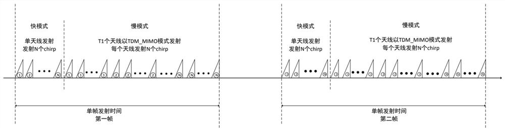
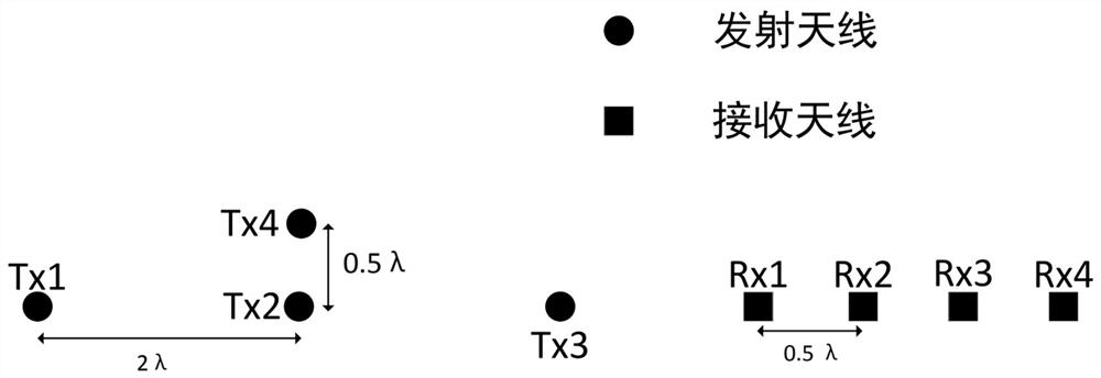
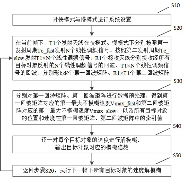
[0061] like Figure 1-2 As shown, the present invention provides a millimeter-wave radar velocity defuzzification method under a MIMO system. The millimeter-wave radar is provided with T1 transmit antennas and R1 receive antennas, and the velocity defuzzification method operates through a preset transmit mode. Among them, the transmission mode includes a fast mode and a slow mode. In the fast mode, any one of the T1 transmitting antennas continuously transmits N chirp signals; in the slow mode, the T1 transmitting antennas are all set to Each time sequence continuously transmits N chirp signals, and the T1 transmit antennas transmit M chirp signals in total.

[0062] In general, a fast mode plus a slow mode constitute a frame. In practical applications, the fast mode can be executed first, and then the slow mode can be executed. Of course, the slow mode can also be executed first and then the fast mode. It depends on the actual situation. Further, the determination of the n...

Embodiment 2

[0099] The present embodiment also provides a processing device including: one or more processors, and a memory. Specifically, the memory is used to store one or more computer programs, and the one or more processors are used to execute the one or more computer programs stored in the memory, so that the one or more processors execute the MIMO system described in Embodiment 1 The mmWave radar velocity deblurring method under . Further, the processing device also includes an output module. The output module is connected to the processor, and is used for outputting the de-blurring result of the millimeter-wave radar velocity de-blurring method under the MIMO system described in the first embodiment.

[0100] Those of ordinary skill in the art can understand that all or part of the features / steps of the above-mentioned method embodiments can be realized by methods, data processing systems or computer programs, and these features may not be implemented in hardware, in software, or...


PUM


Abstract

The invention discloses a millimeter-wave radar velocity defuzzification method and processing equipment under the MIMO system, and relates to the technical field of vehicle-mounted millimeter-wave radars. The millimeter-wave radar of the present invention is provided with T1 transmitting antennas, and the speed defuzzification method operates through a preset transmitting mode; the transmitting mode includes a fast mode and a slow mode, and in the fast mode, select one transmitting antenna from the T1 transmitting antennas Continuously transmit N chirp signals; in the slow mode, each of the T1 transmit antennas continuously transmits N chirp signals at a set timing. Then, the echo signal is processed by using the speed defuzzification algorithm provided by the present invention to realize the speed defuzzification. The method of the invention effectively solves the problem of small unambiguous speed measurement range of the vehicle-mounted millimeter-wave radar under the MIMO system, improves the speed-measurement range of the millimeter-wave radar, and expands the practical value of the MIMO technology in the field of vehicle-mounted millimeter-wave radars.

Description

technical field [0001] The invention relates to the technical field of vehicle-mounted millimeter-wave radar, in particular to a method and processing device for deblurring the speed of a millimeter-wave radar under a MIMO system. Background technique [0002] Millimeter-wave radar has become one of the main sensors in automobiles. The unique advantages of millimeter-wave radar in all-day and all-weather work make it stand out from sensors such as on-board optical cameras and lidars. In addition, compared with lidar, its price Also cheaper. The traditional vehicle-mounted millimeter-wave radar has a small number of transceiver antennas, and generally only one or two transmitting antennas. Its horizontal angular resolution is not high, and it generally does not have the disadvantage of altimetry, which makes its role in the field of assisted driving limited. The widespread use of MIMO (Multiple Input Multiple Output) technology and the emergence of 4D millimeter-wave radar i...

Claims


Application Information

Patent Timeline
Patent Type & Authority Patents(China)
IPC IPC(8): G01S7/41G01S13/58
Inventor 袁鑫豪王闯胡建民周斌
Owner GBA BRANCH OF AEROSPACE INFORMATION RES INST CHINESE ACAD OF SCI
Why Eureka
Try Eureka