
Antenna adjusting structure

A technology for adjusting structures and antennas, applied in the direction of antenna supports/installation devices, etc., can solve problems such as improper installation angles of antennas, poor efficiency of receiving signals by antennas, etc., and achieve the effects of improving convenience, improving efficiency, and reducing errors

Pending Publication Date: 2022-04-12
深圳国人通信技术服务有限公司
View PDF0 Cites 0 Cited by
  • Summary
  • Abstract
  • Description
  • Claims
  • Application Information

AI Technical Summary

Problems solved by technology

[0003] The existing antenna installation is generally fixed on the fixed pole by the staff based on experience, but the angle of the antenna is not a suitable installation angle, resulting in poor efficiency of the antenna receiving signals

Method used


Image

  • Antenna adjusting structure
  • Antenna adjusting structure
  • Antenna adjusting structure

Examples


Embodiment Construction

[0060] 1-7 will be described in further detail below in conjunction with the accompanying drawings.

[0061] The embodiment of the present application discloses an antenna adjustment structure.

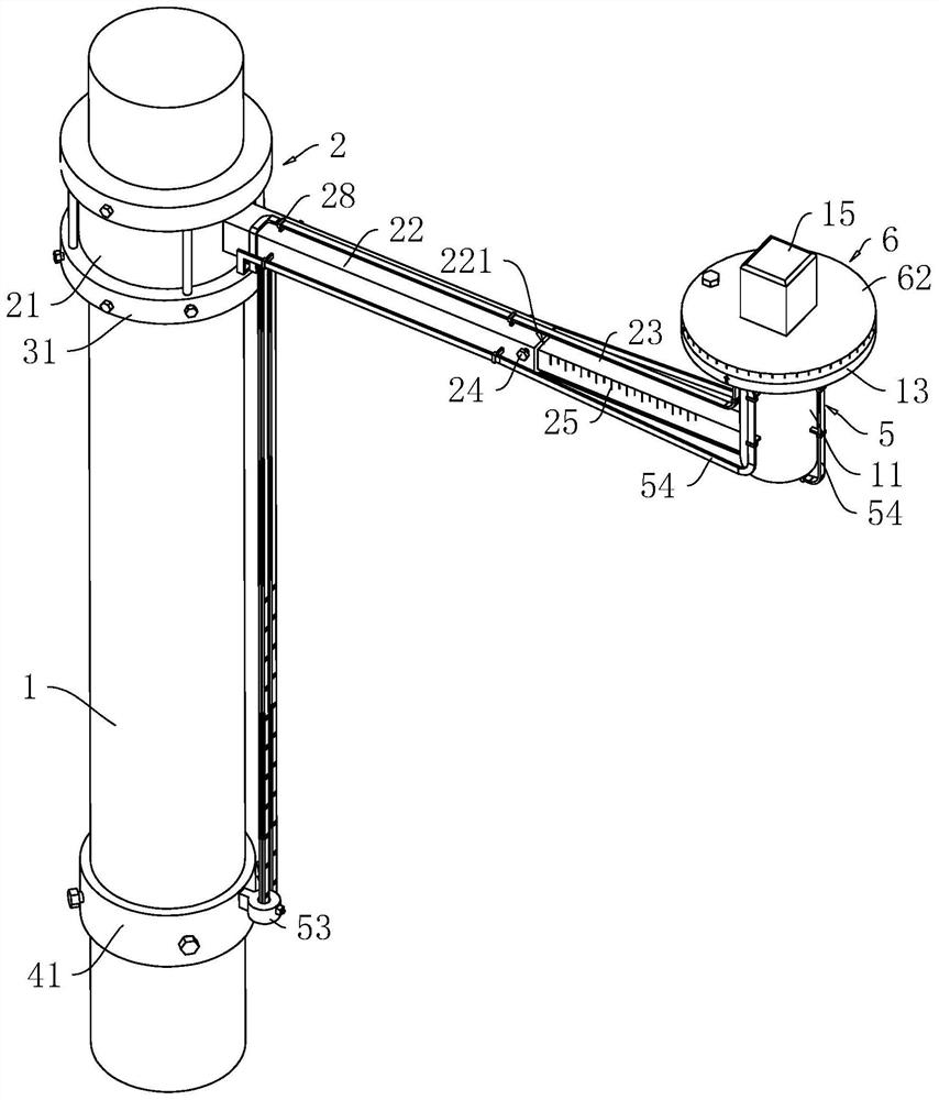
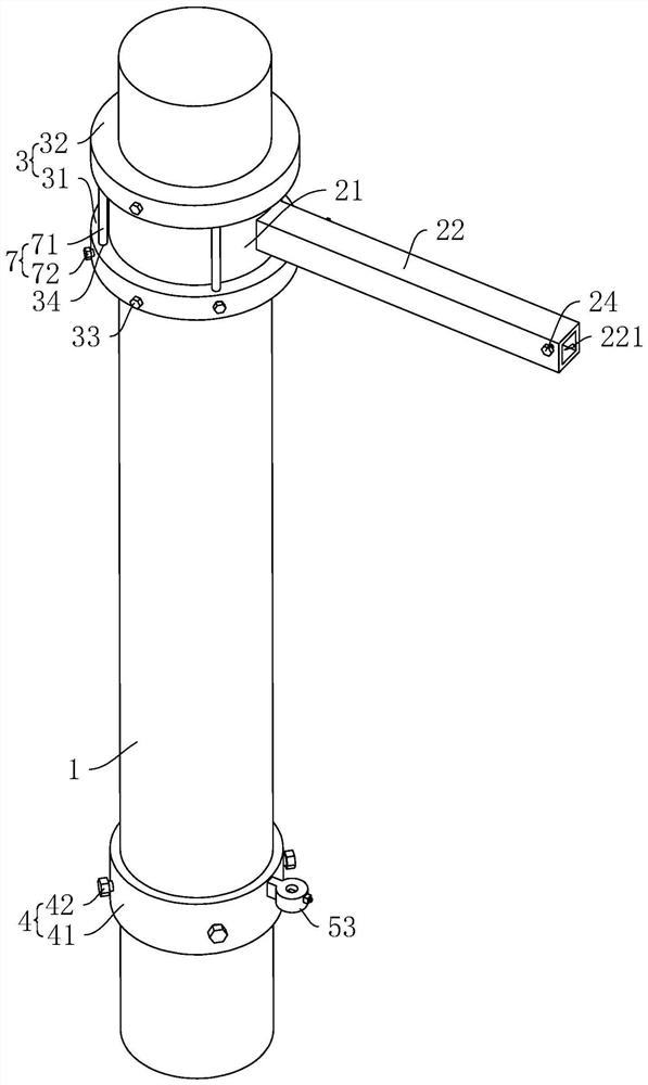
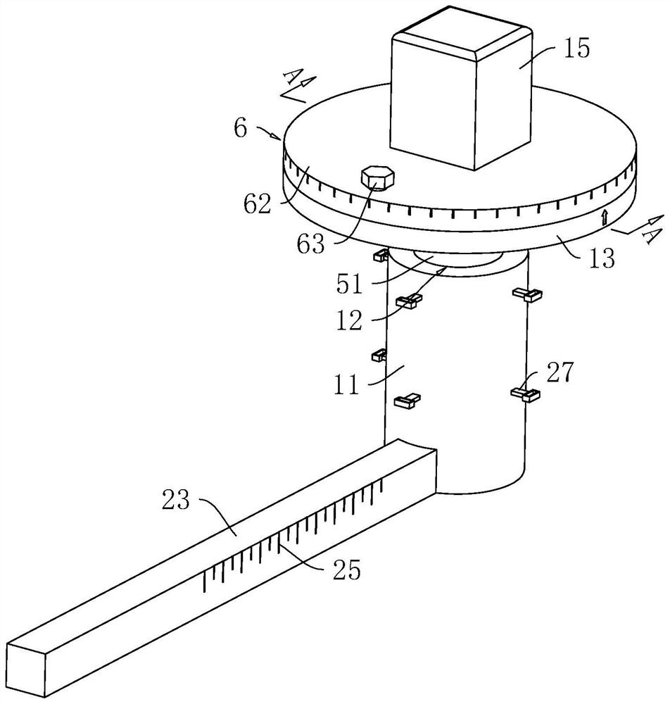
[0062] refer to figure 1 , the antenna adjustment structure includes a vertical fixed rod 1, a mounting column 11 arranged on the fixed rod 1, an adjusting device 2 connected to the mounting column 11 is provided on the fixed rod 1, and a mounting column 11 is rotatably mounted with the antenna The mounting plate 13 connected to the main body 15 is provided with a driving device 5 for driving the mounting plate 13 and the antenna body 15 to rotate on the fixed rod 1 .

[0063] refer to figure 1 and figure 2 , the adjustment device 2 includes a mounting sleeve 21, a connecting rod 22, an adjusting rod 23, and a fixing screw 24. The mounting sleeve 21 is slidably sleeved on the fixing rod 1, and one end of the connecting rod 22 is fixedly installed on the outer wall of the mounting ...


PUM


Abstract

The invention relates to an antenna adjusting structure, and relates to the technical field of antennae, the antenna adjusting structure comprises a mounting column, a mounting plate used for being connected with an antenna body is rotatably mounted on the mounting column, a driving device for driving the mounting plate to rotate is arranged on a fixing rod, a rotating groove is formed in the mounting column, and the driving device comprises a rotating ball and a rotating shaft; the rotating ball is rotationally arranged on the rotating groove and is connected with the mounting plate; and the driving mechanism is arranged on the fixing rod and is used for driving the mounting plate to rotate. According to the invention, the driving mechanism is started to drive the antenna body to rotate to a proper angle, so that the signal receiving efficiency of the antenna body is improved.

Description

technical field [0001] The present application relates to the technical field of antennas, in particular to an antenna adjustment structure. Background technique [0002] With the gradual maturity of antenna application technology, antennas have already entered our daily life. In order to better receive the signal, the antenna installed outdoors needs to be installed at a certain angle for better signal reception. The strength of the signal is related to the signal receiving area. The larger the receiving area, the stronger the signal, so The installation angle of the antenna directly affects the efficiency of receiving signals. [0003] The existing antennas are generally installed on the fixed poles based on the experience of the staff, but the angle of the antenna is not a suitable installation angle, resulting in poor efficiency of receiving signals by the antenna. Contents of the invention [0004] In order to improve the efficiency of receiving signals by the anten...

Claims


Application Information

Patent Timeline
IPC IPC(8): H01Q1/12
Inventor 高东张化增
Owner 深圳国人通信技术服务有限公司
Learn More