Heat-dissipation low-voltage switch cabinet

A low-voltage switchgear and cabinet body technology, applied in the field of low-voltage switchgear, can solve the problems of self-ignition of the electric cabinet, affecting the circuit connection in the electric cabinet, danger, etc., and achieve the effect of accelerating the exchange speed and improving the heat dissipation efficiency

Active Publication Date: 2022-04-12
东营市南方电器有限责任公司
View PDF14 Cites 3 Cited by
  • Summary
  • Abstract
  • Description
  • Claims
  • Application Information

AI Technical Summary

Problems solved by technology

[0002] The low-voltage switchgear is a device that shunts the electricity to each household after the high-voltage electricity is converted into low-voltage electricity by the transformer. The low-voltage switchgear generates heat when the electricity is shunted. When the temperature in the electric cabinet is too high When it is high, it will cause the electric cabinet to ignite spontaneously, causing danger. At the same time, when the low-voltage switchgear is in use, dust will accumulate on it, and the dust will enter the electric cabinet, which will affect the connection of the circuit in the electric cabinet and easily cause short-circuit events.
[0003] However, in order to improve the heat dissipation efficiency of the existing low-voltage switchgear, the heat dissipation fan is generally used for heat dissipation, and the heat dissipation fan is generally installed near the electronic components inside the cabinet. Partial parts of the body dissipate heat, and the hot air in other parts cannot be quickly discharged in a short time

Method used


Image

  • Heat-dissipation low-voltage switch cabinet
  • Heat-dissipation low-voltage switch cabinet
  • Heat-dissipation low-voltage switch cabinet

Examples


Embodiment Construction

[0032] The following will clearly and completely describe the technical solutions in the embodiments of the present invention with reference to the drawings in the embodiments of the present invention.

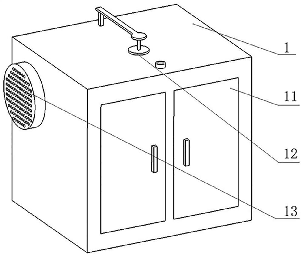
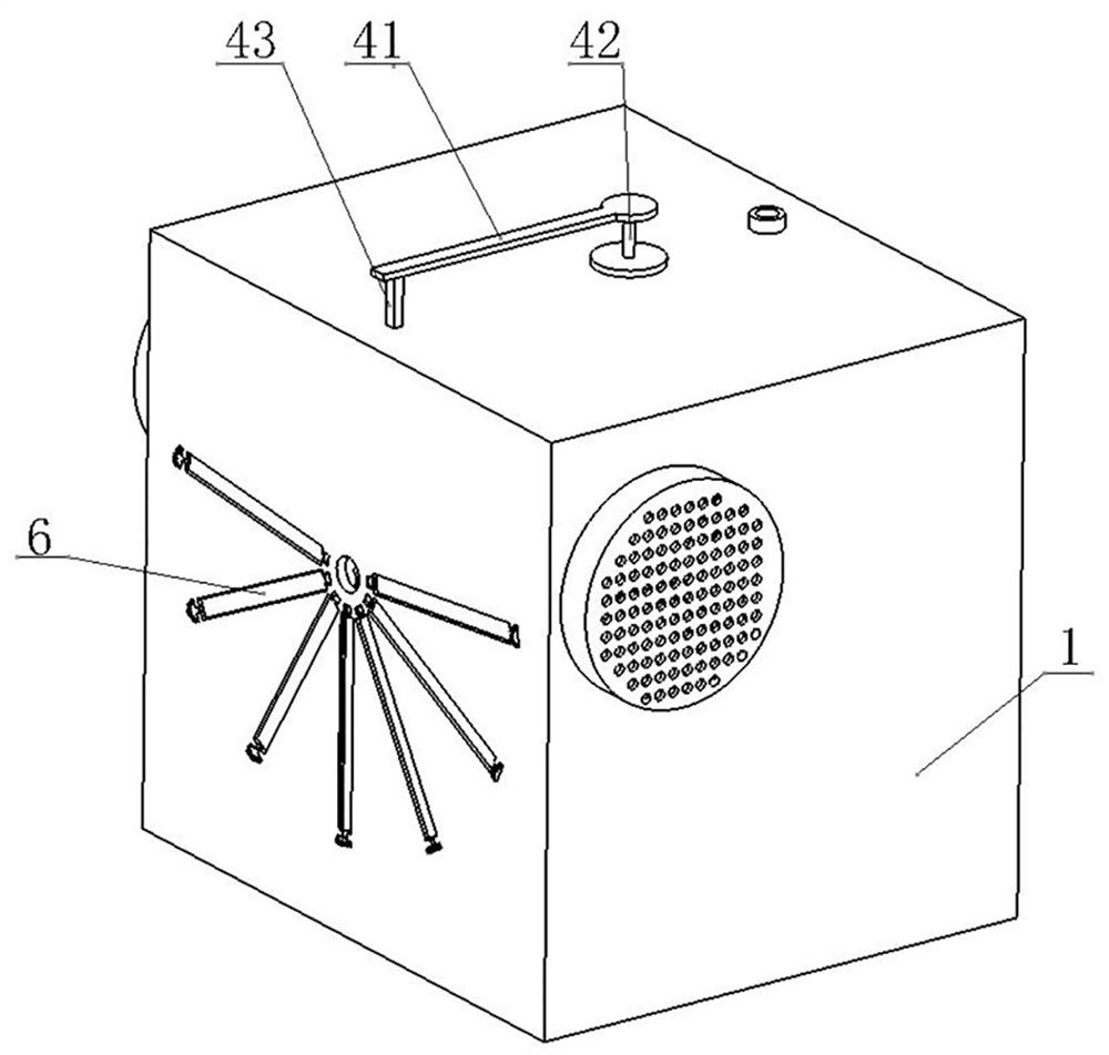
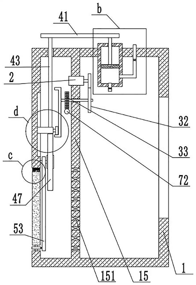
[0033] see Figure 1 to Figure 12 , the present embodiment provides a heat dissipation low-voltage switchgear, including a cabinet body 1, a plurality of mounting holes 14 are provided on the side wall of the cabinet body 1, a partition 15 is installed on the inner wall of the cabinet body 1, and the partition board 15 Ventilation holes 151 are provided on the top, and also include:

[0034] The driving part 2 installed on the partition 15, the driving part 2 includes a driving motor and a driving gear, and the driving motor is connected to the driving gear through a driving shaft;

[0035] The first transmission assembly 3 installed on the partition 15, the first transmission assembly 3 includes a first transmission gear 31 that is movably connected with the driving part 2 a...


PUM


Abstract

The invention discloses a heat dissipation low-voltage switch cabinet, and relates to the technical field of low-voltage switch cabinets, the heat dissipation low-voltage switch cabinet comprises a cabinet body, a driving part, a first transmission assembly, a lifting assembly, a second transmission assembly and a swing assembly, the side wall of the cabinet body is provided with a mounting hole, and the first transmission assembly comprises a first transmission gear and a first transmission rod; the two ends of the first transmission rod are connected with a first transmission gear and a rotating shell correspondingly, the lifting assembly comprises a roller and a sliding block, the roller is installed on the sliding block, a rack plate is further installed on the sliding block, the second transmission assembly comprises a second transmission gear and a rotating plate, and a plurality of meshing teeth are arranged on the surface of the rotating plate. The swing assembly comprises a third transmission gear and an overturning plate, the rotating plate rotating back and forth drives the rotating plate to rotate through meshing connection between meshing teeth and the third transmission gear, and the overturning plate rotating can accelerate the ventilation speed in the mounting hole; the speed of exchange between hot air in the cabinet body and air outside the cabinet body is accelerated, and the heat dissipation efficiency is improved.

Description

technical field [0001] The invention relates to the technical field of low-voltage switch cabinets, in particular to a heat dissipation low-voltage switch cabinet. Background technique [0002] The low-voltage switchgear is a device that shunts the electricity to each household after the high-voltage electricity is converted into low-voltage electricity by the transformer. The low-voltage switchgear generates heat when the electricity is shunted. When the temperature in the electric cabinet is too high When it is high, it will cause the electric cabinet to ignite spontaneously, causing danger. At the same time, when the low-voltage switchgear is in use, dust will accumulate on it, and the dust will enter the electric cabinet, which will affect the connection of the circuit in the electric cabinet and easily cause short-circuit events. [0003] However, in order to improve the heat dissipation efficiency of the existing low-voltage switchgear, the heat dissipation fan is gene...

Claims


Application Information

Patent Timeline
Patent Type & Authority Applications(China)
IPC IPC(8): H02B1/56F16H37/12H02B1/32
Inventor 张利刘毅陈金杰张春红
Owner 东营市南方电器有限责任公司
Why Eureka
Try Eureka