Cable erecting device for electromechanical installation

A technology for installation and cables, applied in the direction of overhead lines/cable equipment, etc., can solve the problems of time-consuming, laborious, troublesome, etc., and achieve the effect of convenient installation

Inactive Publication Date: 2022-04-12
重庆乐尔冷暖设备制造有限公司
View PDF0 Cites 0 Cited by
  • Summary
  • Abstract
  • Description
  • Claims
  • Application Information

AI Technical Summary

Problems solved by technology

[0003] The current cables are manually pulled when erected, which is time-consuming and laborious. When installing at a high place, the cable needs to be pulled up, which is more troublesome. At the same time, the cable needs to be pulled at a high place to install the cable, which makes the construction more difficult.

Method used


Image

  • Cable erecting device for electromechanical installation
  • Cable erecting device for electromechanical installation
  • Cable erecting device for electromechanical installation

Examples


Embodiment 1

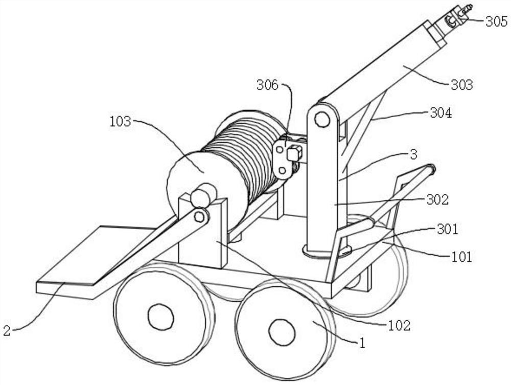
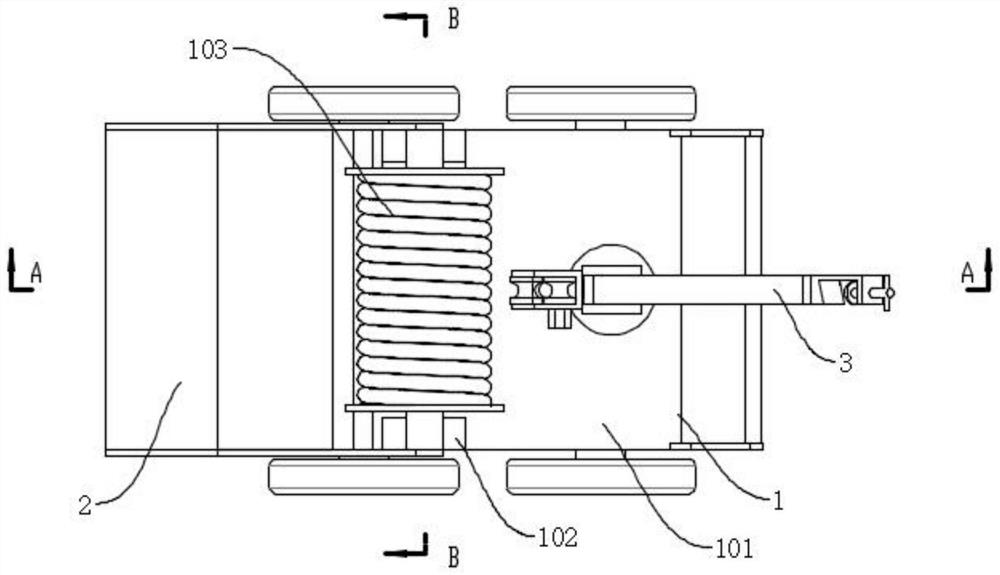
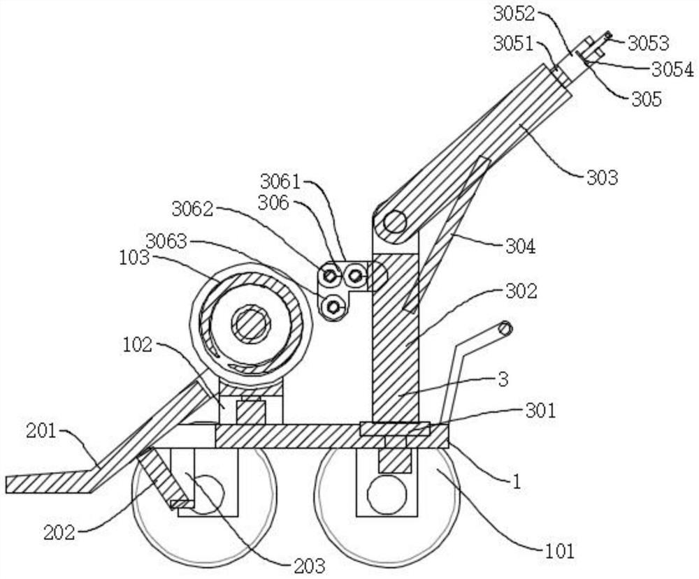
[0033] Such as Figure 1-Figure 8As shown, a cable erection device for electromechanical installation of the present invention includes a moving mechanism 1. The moving mechanism 1 is mainly composed of a moving trolley 101, a vertical plate 102, and a cable 103, and also includes an auxiliary feeding mechanism 2 and a lifting mechanism 3. The auxiliary feeding mechanism 2 includes a rotating plate 201, a first driving cylinder 202, and a mounting frame 203. One end of the rotating plate 201 is rotationally connected to the outside of the vertical plate 102, the other end of the rotating plate 201 is provided with a bending portion, and the bottom of the rotating plate 201 is rotationally connected At the output end of the first driving cylinder 202, the fixed end of the first driving cylinder 202 is connected to the inside of the mounting frame 203 in rotation, and the mounting frame 203 is connected to the bottom of the mobile trolley 101 by bolts. The pulling mechanism 3 inc...

Embodiment 2

[0036] Such as Figure 5 As shown, the difference between Embodiment 2 and Embodiment 1 is that an auxiliary unloading mechanism 4 is provided at the bottom of the cable 103, and the auxiliary unloading mechanism 4 includes a supporting plate 401 and a spring 41, and the supporting plate 401 is arranged at the bottom of the cable 103 The front and rear ends of the bottom of the supporting plate 401 are fixedly connected with springs 41, and the lower end of the spring 41 is connected to the top of the mobile trolley 101 by bolts. In this way, the spring 41 can drive the supporting plate 401 to rise, and the supporting plate 401 squeezes the cable 103, making it more labor-saving. The cable 103 is taken out from the inside of the arc-shaped groove to realize the function of assisting the removal of the cable 103 .

[0037] In the above structure, when the cable 103 is installed, the cable 103 is first moved to the top of the rotating plate 201, and then the rotating plate 201 i...


PUM


Abstract

The invention discloses a cable erecting device for mechanical and electrical installation, which comprises a moving mechanism, the moving mechanism is mainly composed of a moving trolley, a vertical plate and a cable, the cable erecting device further comprises an auxiliary feeding mechanism and a pulling-up mechanism, the auxiliary feeding mechanism comprises a rotating plate, a first driving cylinder and a mounting frame, one end of the rotating plate is rotatably connected to the outer side of the vertical plate, and the other end of the rotating plate is rotatably connected to the outer side of the vertical plate; and a bending part is arranged at the other end of the rotating plate, and the bottom of the rotating plate is rotationally connected to the output end of the first driving air cylinder. When a cable is installed, the cable is moved to the top of the rotating plate, then the rotating plate is driven to rotate through the first driving air cylinder, the rotating plate drives the cable to roll to the top of the vertical plate, and the function of assisting cable installation is achieved; according to the arrangement, the pulling assembly can pull the cable, manual pulling is not needed, time and labor are saved, the cable can be clamped through the clamping assembly, the cable does not need to be pulled when the cable is installed, and installation is more convenient.

Description

technical field [0001] The invention relates to the technical field of cable erection, in particular to a cable erection device for electromechanical installation. Background technique [0002] The cable is usually a rope-like cable twisted by several or several groups of wires (at least two in each group). Each group of wires is insulated from each other and is often twisted around a center. Highly insulating overlay. The cable has the characteristics of internal electrification and external insulation. Cables include power cables, control cables, compensation cables, shielded cables, high-temperature cables, computer cables, signal cables, coaxial cables, fire-resistant cables, marine cables, mining cables, aluminum alloy cables, etc. They are all composed of single or multi-strand wires and insulation layers, and are used to connect circuits, electrical appliances, etc. [0003] The current cables are manually pulled when erected, which is time-consuming and laborious....

Claims


Application Information

Patent Timeline
Patent Type & Authority Applications(China)
IPC IPC(8): H02G1/04
Inventor 贺昌全黄光宇黄中仁
Owner 重庆乐尔冷暖设备制造有限公司
Why Eureka
Try Eureka