
Automatic angle adjusting and self-locking structure of photovoltaic support

A technology of photovoltaic support and self-locking structure, which is applied in the supporting structure of photovoltaic modules, photovoltaic power generation, photovoltaic modules and other directions, can solve the problems of easy wear and damage of joints, increased maintenance costs, insufficient structural strength, etc., and achieves fast and convenient installation. , the effect of improving stability and reducing costs

Active Publication Date: 2022-04-12
徐州日托光伏科技有限公司
View PDF9 Cites 1 Cited by
  • Summary
  • Abstract
  • Description
  • Claims
  • Application Information

AI Technical Summary

Problems solved by technology

[0005] The top plate is fixedly installed through the second connecting rope, the structural strength is not enough, and the guide wheel used to tighten the second connecting rope has a degree of freedom of rotation; Abrasion damage, later repair and maintenance costs are greatly increased

Method used


Image

  • Automatic angle adjusting and self-locking structure of photovoltaic support
  • Automatic angle adjusting and self-locking structure of photovoltaic support
  • Automatic angle adjusting and self-locking structure of photovoltaic support

Examples


Embodiment Construction

[0026] Next, the technical solutions in the embodiments of the present invention will be described in connection with the drawings of the embodiments of the present invention, and it is understood that the described embodiments are merely the embodiments of the present invention, not all of the embodiments. Based on the embodiments of the present invention, all other embodiments obtained by those of ordinary skill in the art are in the range of the present invention without making creative labor premise.

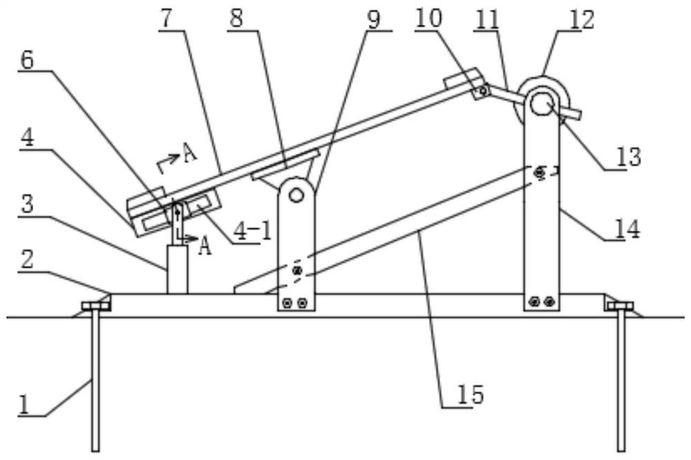
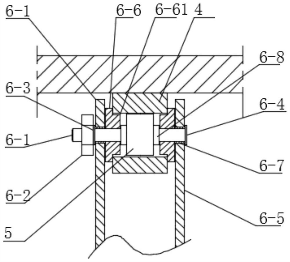
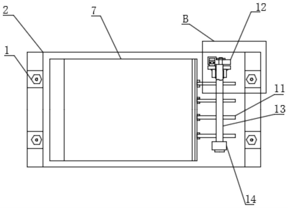
[0027] Such as Figure 1 to 4 As shown, a photovoltaic stent automatic angle self-locking structure is used, and the base 2 adopts a frame structure, and the side of the base 2 is inclined. The base 2 is opened on the slope, and an anchor bolt is mounted in the sink, and the stability of the base 2 is secured by the anchor bolt 1. The lower end of the main bracket 9 and the auxiliary support 14 is fixed between the base 2, and the oblique strut 15 is fixed between the main bracke...


PUM


Abstract

The invention discloses an automatic angle adjusting and self-locking structure of a photovoltaic support, and belongs to the technical field of photovoltaic power generation. Comprising a base, a main support, an auxiliary support and a lifting device. A main support is rotationally mounted at the upper end of the main bracket, and a mounting plate is fixed on the main support; a guide slide rail is fixed at one end of the mounting plate, a roller is slidably mounted on the guide slide rail, and the upper end of the lifting device is connected with the roller; a row of sliding rods are hinged to the mounting plate far away from the guide sliding rails; a rotating shaft is rotationally mounted at the upper end of the auxiliary support and provided with radial through holes in one-to-one correspondence with the sliding rods, and the sliding rods are mounted in the corresponding radial through holes of the rotating shaft in a sliding fit mode; and a locker is arranged between one end of the rotating shaft and the auxiliary support. The inclination angle of the mounting plate is adjusted through the lifting device, the lifting device is provided with a displacement sensor, and the actual inclination angle of the mounting plate can be determined and adjusted; locking of the mounting plate is achieved through the locker, the lifting device and the auxiliary support are arranged on the two sides of the main support and both have the locking effect, and the stability of the mounting plate is improved.

Description

Technical field [0001] The present invention relates to the field of photovoltaic power generation technologies, and in particular, a photovoltaic stent automatic angle self-locking structure. Background technique [0002] Photovoltaic power generation is a technique that directly transforms light energy into electrical energy using the optical vod effects of the semiconductor interface. It is mainly composed of three parts of photovoltaic power generation board, controller and inverter. The photovoltaic mounting bracket is an important part of the photovoltaic system for installing the solar panel. The tilt angle of the solar panel is closely related to the absorption rate of the light energy, so the existing photovoltaic mounting brackets generally need to increase the power generation efficiency according to the time range. [0003] China's patent discloses a photovoltaic power mounting frame (CN212258865U), including the mounting of the bottom plate, and the right side fixed ...

Claims


Application Information

Patent Timeline
Patent Type & Authority Applications(China)
IPC IPC(8): H02S20/30F24S30/425F24S25/63
CPCY02E10/50
Inventor 马丁格林张凤鸣
Owner 徐州日托光伏科技有限公司
Learn More