Connecting piece, bent arm and bone conduction earphone
A technology of connecting parts and curved arms, applied in the directions of earpieces/headphone accessories, etc., can solve the problems of affecting the wearing experience of headphones, reducing the clamping effect, loosening the lock structure, etc., achieving excellent fixing effect, improving stability, and fast setting. Effect
- Summary
- Abstract
- Description
- Claims
- Application Information
AI Technical Summary
Problems solved by technology
Method used
Image
Examples
Embodiment 1
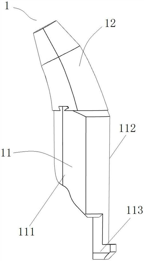
[0051] Refer to attached figure 1As shown, the connector of the present invention includes a rigid main body 1, the main body 1 includes a straight line segment 11 and an arc line segment 12, and the straight line segment 11 and the arc line segment 12 are integrally molded to define the main body 1 The straight line segment 11 extends out of the hook structure 113 in a direction away from the arc segment 12, and the bending direction of the arc segment 12 is opposite to the hooking direction of the hook structure 113. The tangential area of the arc segment 12 decreases gradually along the direction away from the straight segment 11 .
[0052] In a preferred embodiment, as attached figure 1 As shown, the main body 1 as a whole presents an oblate or type oblate structure, and the cross section of the main body 1 can be oblate or elliptical if cut horizontally at any position in the horizontal direction on the figure. The straight line section 11 means that a section of the ...
Embodiment 2
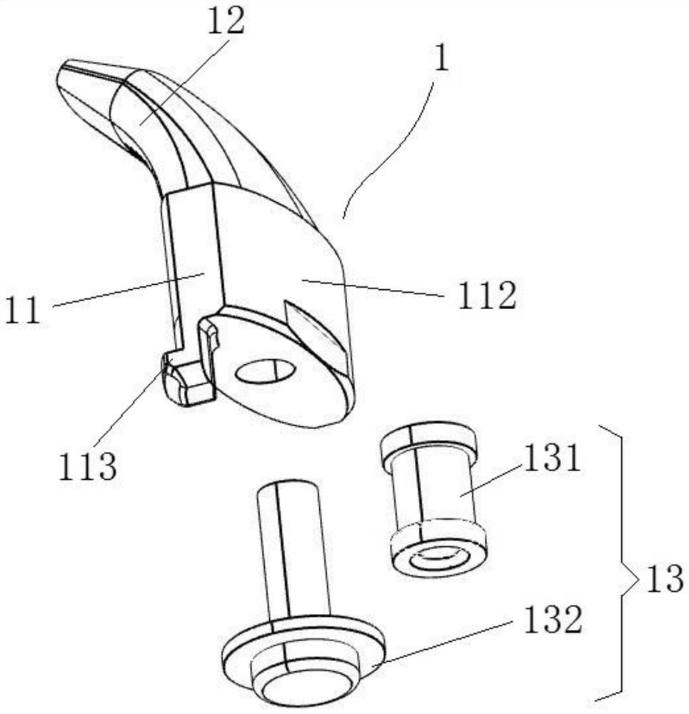
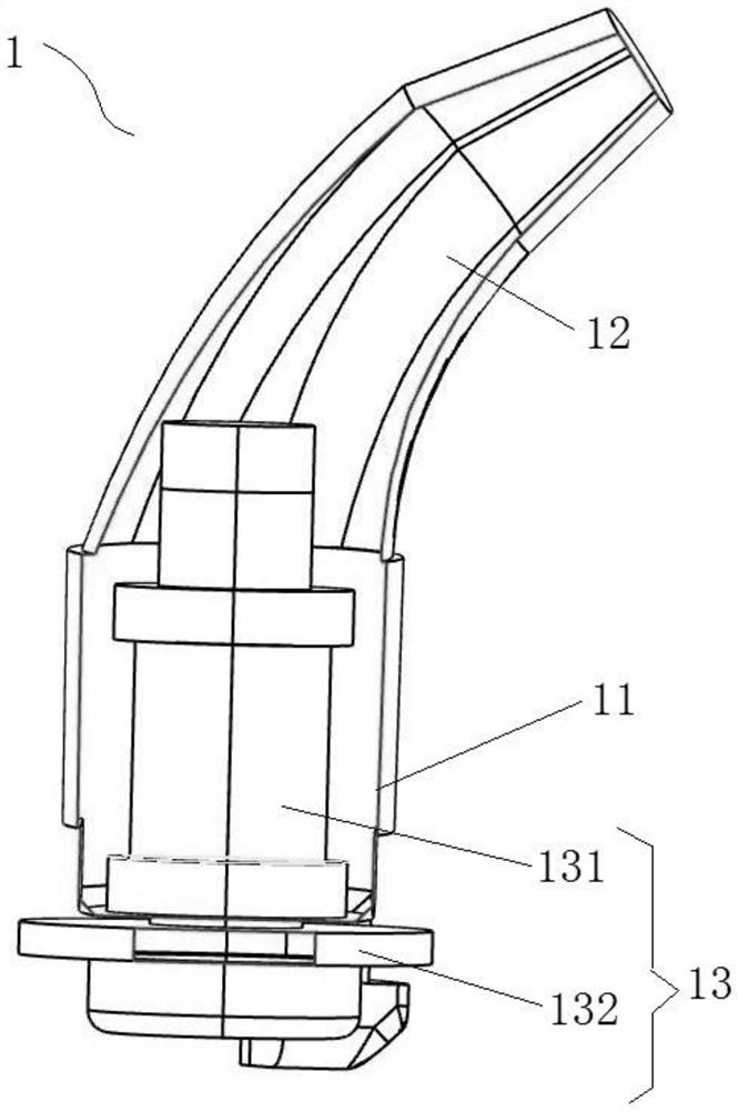
[0055] The difference between the present embodiment and the first embodiment is only that the inside of the straight line section 11 is a hollow structure, and the locking member 13 is embedded therein. The other technical solutions are the same or similar to those of the first embodiment, so the details of this embodiment will not be repeated.
[0056] Refer to attached figure 2 And attached image 3 As shown, the rigid body 1 of the connector of the present invention includes a straight line section 11 and an arc line section 12 , which are integrally formed by transition, wherein the straight line section 11 is embedded with a locking piece 13 . Specifically, the outside of the straight section 11 is a hard shell, and the inner hollow is fixed with a locking piece 13. By designing the locking piece 13, the connecting piece of the present invention can realize the connection effect by locking. Preferably, the locking member 13 includes a locking hole 131 and a locking pin...
Embodiment 3
[0058] The difference between this embodiment and Embodiment 1 and Embodiment 2 is that the connector of the present invention is composed of a set of hard bodies, and other technical solutions are the same or similar to Embodiment 1, so this embodiment will not repeat them.
[0059] Refer to attached Figure 4 As shown, the connecting piece of the present invention is composed of a group of symmetrically arranged rigid bodies, and the two bodies 1 can be completely identical, or can be set to be partially similar in appearance, or the two bodies 1 can be respectively designed as the technology of the first embodiment The technical scheme of scheme and embodiment two. As shown in the figure, the connector includes a first body 101 and a second body 102, the first body 101 and the second body 102 are a set of opposite bodies 1, wherein the first body 101 The straight section 11 is a solid structure, and the second body 102 is embedded with a locking member 13 . Wherein, the d...
PUM
 Abstract
Description
Claims
Application Information
 - R&D
- Intellectual Property
- Life Sciences
- Materials
- Tech Scout
- Unparalleled Data Quality
- Higher Quality Content
- 60% Fewer Hallucinations
Browse by: Latest US Patents, China's latest patents, Technical Efficacy Thesaurus, Application Domain, Technology Topic, Popular Technical Reports.
© 2025 PatSnap. All rights reserved.Legal|Privacy policy|Modern Slavery Act Transparency Statement|Sitemap|About US| Contact US: help@patsnap.com


