Preoperative appliance sterile equipment for surgical operation

A technology for surgical operations and chemical equipment, applied in the field of aseptic equipment for instruments, can solve the problems of difficult collection and disinfection methods, singleness, etc., and achieve the effect of avoiding incomplete disinfection and easy collection

Pending Publication Date: 2022-04-15
陈安林
View PDF6 Cites 0 Cited by
  • Summary
  • Abstract
  • Description
  • Claims
  • Application Information

AI Technical Summary

Problems solved by technology

[0005] Aiming at the deficiencies of the prior art, the present invention provides a high-efficiency disinfection and easy-to-collect aseptic equipment for preoperative instruments for surgical operations, so as to overcome the shortcomings of the existing aseptic equipment that are difficult to collect and have a single disinfection method

Method used


Image

  • Preoperative appliance sterile equipment for surgical operation
  • Preoperative appliance sterile equipment for surgical operation
  • Preoperative appliance sterile equipment for surgical operation

Examples


Embodiment 1

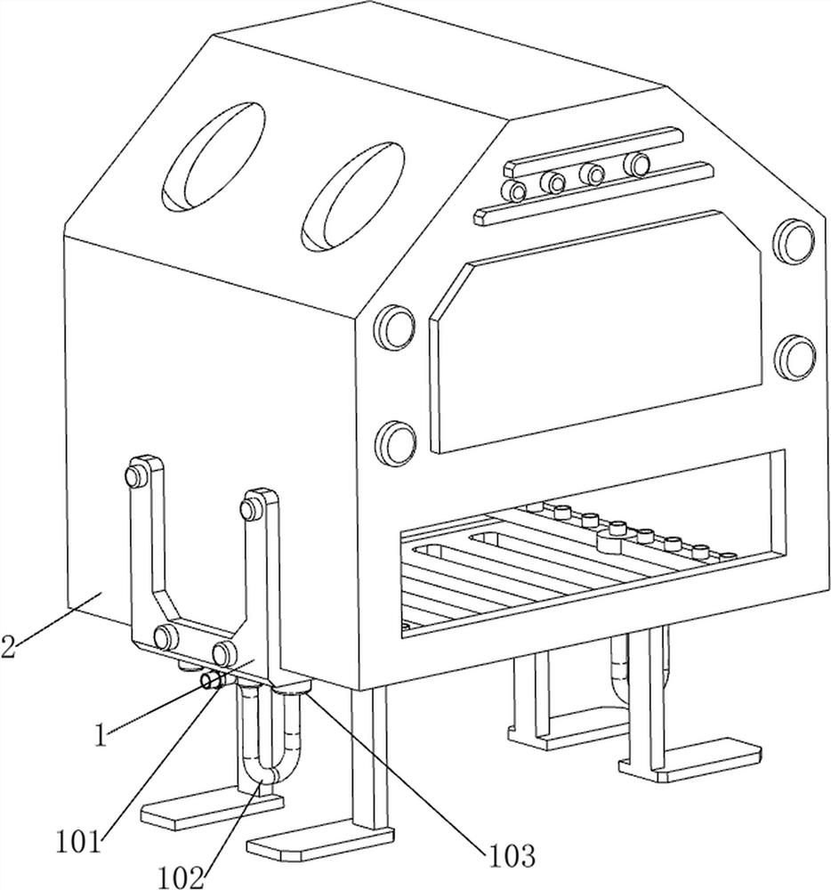
[0038] A kind of aseptic equipment for preoperative instruments for surgical operations, now refer to Figure 1-3 , including a bottom frame 1, a shell 2, a support plate 21, a contact switch 4, an ultraviolet lamp 5, a first slide bar 6, a first spring 7, a fixed frame 8, a pull frame 94, a filter screen 96, a pull mechanism 9, a steam The disinfection mechanism 10, the pushing mechanism 11 and the moving mechanism 12, the shell 2 is fixedly connected between the upper sides of the two bottom frames 1 by bolts, and the bottoms of the two bottom frames 1 are connected with two support plates 21 symmetrically front and back, and the front of the shell 2 A contact switch 4 is arranged on the right side of the upper side of the upper part, and a first slide bar 6 is provided on the left and right sides of the casing 2, and an ultraviolet lamp 5 is slidably connected between the two first slide bars 6, and the ultraviolet lamp 5 is used for The utensil is sterilized, the first spr...

Embodiment 2

[0045] On the basis of embodiment 1, now refer to Figure 14 , also includes a drainage mechanism 13, the drainage mechanism 13 includes a sewage pool 131, a liquid level sensor 132 and a solenoid valve 133, a sewage pool 131 is connected between the lower sides of the two chassis 1, and the sewage pool 131 is used to collect excess sewage A liquid level sensor 132 is provided on the front side of the sewage tank 131 , and a solenoid valve 133 is provided on the lower side of the rear part of the sewage tank 131 .

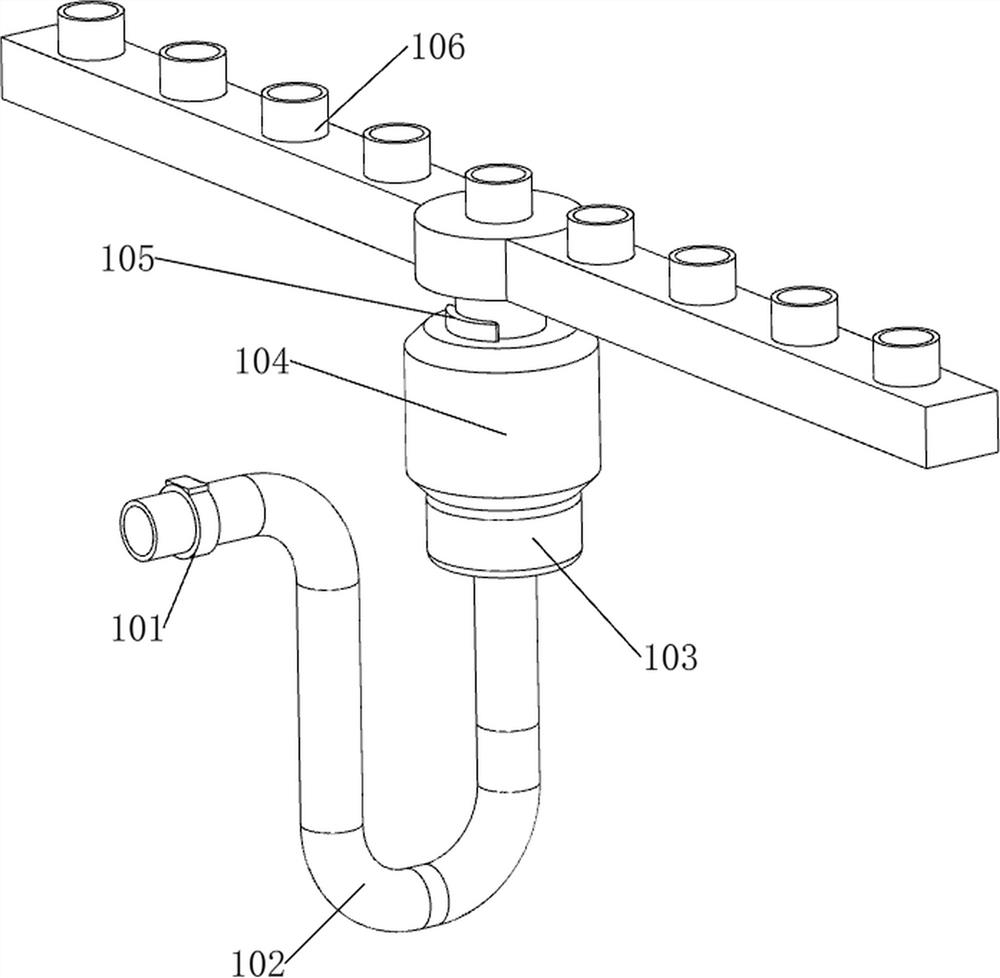
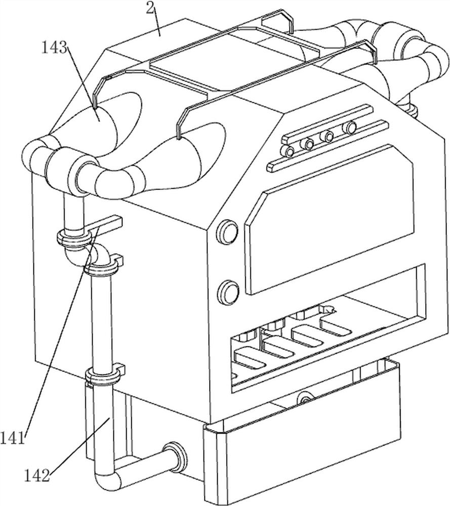
[0046] now refer to Figure 15-16 , also includes a steam export mechanism 14, the steam export mechanism 14 includes a third installation block 141, a pipe 142, a heat dissipation pipe 143, a second installation frame 144 and a fan group 145, and three third installations are arranged on the left and right sides of the casing 2. Block 141, pipes 142 are connected between the three third installation blocks 141 on the same side and the sewage pool 131, heat dissip...


PUM


Abstract

The invention relates to instrument sterility equipment, in particular to preoperative instrument sterility equipment for a surgical operation. The preoperative instrument sterilisation equipment for the surgical operation is efficient in disinfection and easy to collect. The preoperative instrument sterile equipment comprises a bottom frame, a shell, a supporting plate, a contact switch, an ultraviolet lamp, a first sliding rod, a first spring, a fixing frame, a filter screen, a pulling frame, a pulling mechanism, a steam disinfection mechanism and the like. A shell is connected between the upper sides of the two bottom frames, two supporting plates are connected to the bottoms of the two bottom frames in a front-back symmetry mode, a contact switch is arranged on the right side of the upper side of the front portion of the shell, and first sliding rods are arranged on the left side and the right side in the shell. The water pump is started to guide water into the steam spray head through the water pipe, in the flowing process, the heating module heats the water, then steam is sprayed to an appliance through the steam spray head, and meanwhile the ultraviolet lamp moves to conduct ultraviolet disinfection on the appliance.

Description

technical field [0001] The present invention relates to an instrument aseptic device, in particular to a preoperative instrument aseptic device for surgical operations. Background technique [0002] Surgical instruments refer to the medical instruments used in clinical operations. In order to avoid the breeding and spread of bacteria and viruses during the operation, surgical instruments need to be disinfected before use. Since most of the existing surgical instruments are relatively sharp, if using Manual cleaning and disinfection can easily injure fingers and cause secondary infection, and manual cleaning is time-consuming and laborious, and the cleaning quality cannot be guaranteed. Most of the existing aseptic equipment uses the method of soaking in disinfectant solvents. This type of disinfection method is relatively ineffective. Single, inefficient, and when people collect surgical instruments, people need to collect the instruments from the disinfection solvent, which...

Claims


Application Information

Patent Timeline
Patent Type & Authority Applications(China)
IPC IPC(8): A61L2/10A61L2/07A61L2/26A61L2/24
CPCA61L2/10A61L2/07A61L2/26A61L2/24A61L2202/24A61L2202/14
Inventor 陈安林
Owner 陈安林
Why Eureka
Try Eureka