
Pressure vessel, compressor, air conditioning equipment and vehicle

A pressure vessel, high pressure technology, applied in the field of air conditioning equipment, can solve the problems of flow to the outside, leakage, large sealing pressure difference, etc., to achieve the effect of improving sealing performance, reducing sealing pressure difference, and ensuring sealing performance

Pending Publication Date: 2022-04-15
ANHUI WELLING AUTO PARTS CO LTD +1
View PDF0 Cites 0 Cited by
  • Summary
  • Abstract
  • Description
  • Claims
  • Application Information

AI Technical Summary

Problems solved by technology

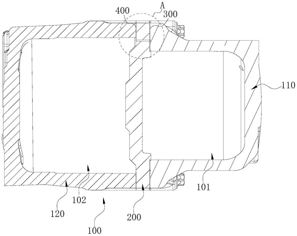
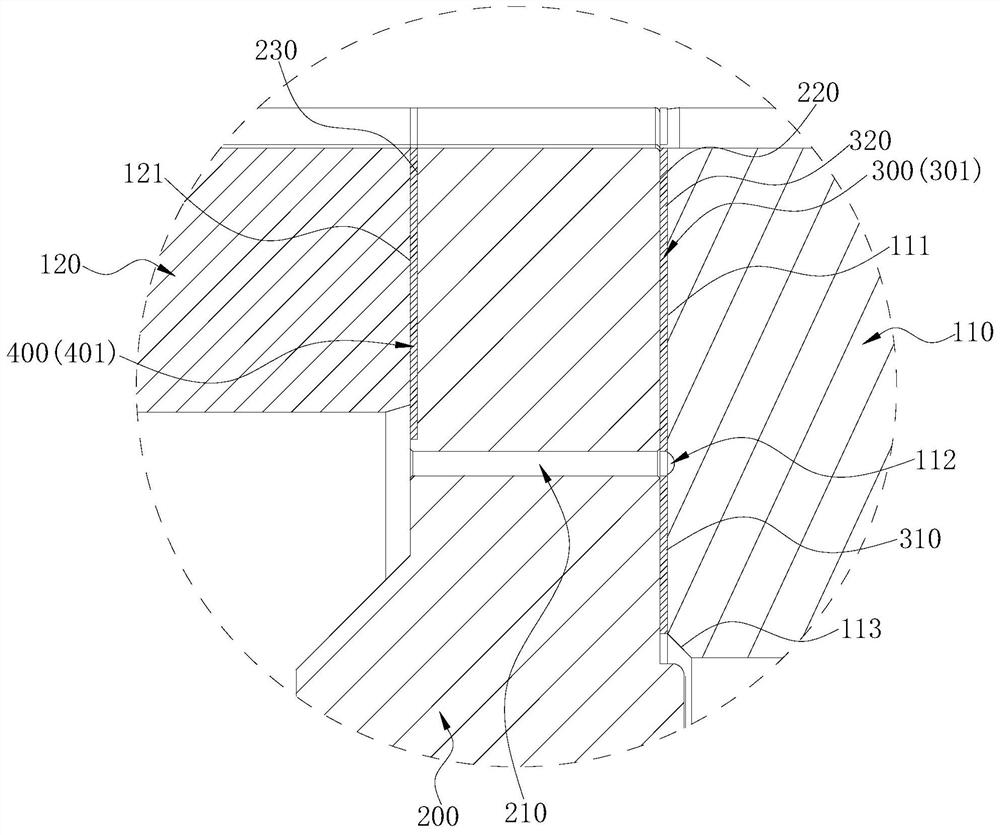
[0003] The purpose of the embodiments of the present application is to provide a pressure vessel, a compressor, an air conditioner, and a vehicle to solve the problem in the prior art that when the pressure in the high-pressure chamber of the shell is high, the sealing pressure difference between the high-pressure chamber and the outside world is relatively small. Large, the high-pressure fluid in the high-pressure chamber is easy to flow from the gap between the high-pressure chamber and the partition plate to the outside, causing technical problems of leakage

Method used


Image

  • Pressure vessel, compressor, air conditioning equipment and vehicle
  • Pressure vessel, compressor, air conditioning equipment and vehicle
  • Pressure vessel, compressor, air conditioning equipment and vehicle

Examples


Embodiment Construction

[0032] In order to make the technical problems, technical solutions and beneficial effects to be solved by the present application clearer, the present application will be further described in detail below in conjunction with the accompanying drawings and embodiments. It should be understood that the specific embodiments described here are only used to explain the present application, and are not intended to limit the present application.

[0033] It should be noted that when an element is referred to as being “fixed” or “disposed on” another element, it may be directly on the other element or be indirectly on the other element. When an element is referred to as being "connected to" another element, it can be directly connected to the other element or indirectly connected to the other element.

[0034] It is to be understood that the terms "length", "width", "top", "bottom", "front", "rear", "left", "right", "vertical", "horizontal", "top" , "bottom", "inner", "outer" and oth...


PUM


Abstract

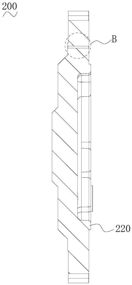
The invention provides a pressure container, a compressor, air conditioning equipment and a vehicle, the pressure container comprises a high-pressure shell, a low-pressure shell and a partition plate, the partition plate is arranged between the high-pressure shell and the low-pressure shell, a high-pressure cavity is defined by the high-pressure shell and the partition plate, and a low-pressure cavity is defined by the low-pressure shell and the partition plate; a sealing structure is arranged between the high-pressure shell and the partition plate, a through hole is formed in the partition plate and communicates with the low-pressure cavity, and the sealing structure comprises a high-pressure sealing structure and a low-pressure sealing structure. According to the pressure container, the partition plate is provided with the through hole communicating with the low-pressure cavity, the pressure between the high-pressure sealing structure and the low-pressure sealing structure can be reduced, the sealing pressure difference between the high-pressure shell and the outside is greatly reduced, and the sealing performance is improved; if the fluid in the high-pressure cavity can permeate the high-pressure sealing structure, the fluid can flow to the low-pressure cavity through the through hole, and the problem that the pressure of the high-pressure side is too high to cause leakage to the outside can be effectively avoided.

Description

technical field [0001] The present application belongs to the technical field of air conditioning equipment, and more specifically relates to a pressure vessel, a compressor, an air conditioning equipment and a vehicle. Background technique [0002] Compressors used in air conditioners generally have a high-pressure chamber and a low-pressure chamber inside the shell, and a partition plate is usually provided between the high-pressure chamber and the low-pressure chamber. Sealing, when the pressure in the high-pressure chamber is high, the sealing pressure difference between the high-pressure chamber and the outside world is large, and the seal is prone to deformation in a high-pressure environment, and a gap is easily formed between the high-pressure chamber and the partition plate. The high-pressure fluid easily flows from the gap to the outside, causing leakage. The leaked fluid will cause damage to the external environment. At the same time, the leakage may cause the los...

Claims


Application Information

Patent Timeline
Patent Type & Authority Applications(China)
IPC IPC(8): F16J15/16F16J15/32F16J15/3268F16J15/3284F04B39/00
Inventor 黎法运杨开成
Owner ANHUI WELLING AUTO PARTS CO LTD
Learn More