Fluid dynamic pressure type rear isolation sealing device for mechanical dry gas seal of turbine

A technology of dry gas sealing and turbomachinery, which is applied to parts of pumping devices for elastic fluids, engine seals, mechanical equipment, etc., and can solve dry gas seal failure, poor return oil flow, non-contact Problems such as large static leakage of carbon ring seals

Pending Publication Date: 2020-06-05
上海优赛密封科技有限公司
View PDF0 Cites 0 Cited by
  • Summary
  • Abstract
  • Description
  • Claims
  • Application Information

AI Technical Summary

Problems solved by technology

Sometimes the carbon and graphite powder worn down during the running-in period may cause the failure of the outer seal of the dry gas seal
The static leakage of the non-contact carbon ring seal is too large, and the consumption of the isolation gas is very sensitive to the temperature of the carbon ring seal
For some special working conditions, such as the axial distance between the bearing and the dry gas seal is too close; the position of the oil discharge port of the bearing is unreasonably designed; the oil inlet pressure of the bearing is too high; the oil return port of the bearing box is too small, and the oil return flow is not smooth, etc. Both the labyrinth seal and the carbon ring seal may have a short circuit of the isolated gas, causing the bearing lubricating oil or lubricating oil gas to enter the outer seal of the dry gas seal, pollute the dry gas seal, and cause the dry gas seal to fail

Method used


Image

  • Fluid dynamic pressure type rear isolation sealing device for mechanical dry gas seal of turbine
  • Fluid dynamic pressure type rear isolation sealing device for mechanical dry gas seal of turbine
  • Fluid dynamic pressure type rear isolation sealing device for mechanical dry gas seal of turbine

Examples


Embodiment 1

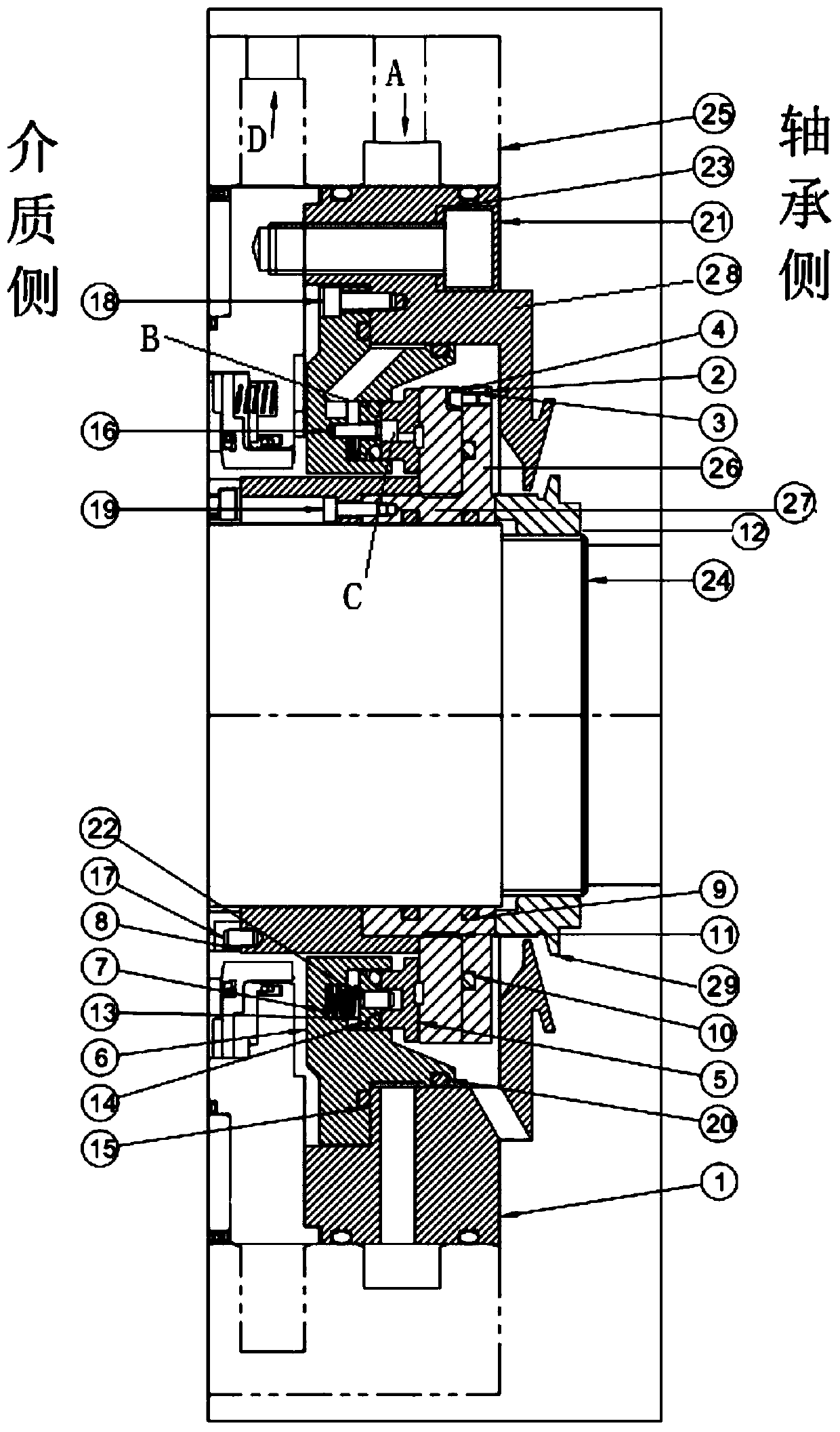
[0040] A fluid dynamic pressure type rear isolation sealing device for dry gas sealing of turbomachinery, its structure is as follows figure 1 As shown, the sealing device is between the dry gas seal assembly and the bearing housing, and consists of two parts: a rotating assembly and a stationary assembly.

[0041] The rotating assembly includes a moving ring 4, a shaft sleeve 2, a compression sleeve 8, a centering corrugated belt 11, a number of O-rings, a transmission pin 3, a number of hexagon socket screws, etc., wherein the compression sleeve 8 is connected to the shaft sleeve through the hexagon socket screw. 2 are connected as a whole, specifically, the shaft sleeve 2 includes a coaxial and integrated first ring 26 and a second ring 27, a groove is provided at the tail end of the compression sleeve 8 and in contact with the main shaft 24, the first The front end of the ring 26 is inserted into the groove and abuts against the groove wall, the bottom of the groove is fix...


PUM


Abstract

The invention relates to a fluid dynamic pressure type rear isolation sealing device for a mechanical dry gas seal of a turbine. The rear isolation sealing device is disposed between a dry gas sealingassembly and a bearing box, the rear isolation sealing device comprises a rotating assembly and a static assembly, and a spindle is provided with a locking nut, wherein the two ends of the rotating assembly are clamped by the locking nut and the rotating portion of the dry gas sealing assembly respectively. The rotating assembly is arranged on the outer side of the spindle in a sleeving manner and rotates at a high speed with the spindle, the static assembly is arranged around the spindle and is fixed to the shell, one end face of the rotating assembly and one end face of the static assemblyare attached to form a sealing surface, the sealing surface is perpendicular to the axial direction of the spindle, and a fluid dynamic pressure groove is formed in the end face of the rotating assembly. Compared with the prior art, the sealing device is applied to the turbine, leakage of lubricating oil on the bearing side to the dry gas seal can be avoided, and the loss of isolation gas is extremely small.

Description

technical field [0001] The invention relates to the technical field of mechanical seals, in particular to a fluid dynamic pressure rear isolation sealing device for dry gas seals of turbomachinery. Background technique [0002] Turbomachinery includes turbocompressors (such as centrifugal compressors, axial flow compressors) and turboexpanders, which are high-speed rotating equipment and are also the core key equipment of petroleum, chemical and other equipment. At present, dry gas seals are commonly used in turbomachinery, that is, dry-running, gas-lubricated, non-contact mechanical seals, as their shaft end seals. Whether it is a single-end dry gas seal, double-end dry gas seal, tandem dry gas seal, or tandem dry gas seal with a middle labyrinth, it is necessary to use a rear isolation seal to isolate the dry gas seal from the bearing box to prevent the bearing box from Lubricating oil produced by the high-speed rotation of the main shaft pollutes the outer seal of the dr...

Claims


Application Information

Patent Timeline
Patent Type & Authority Applications(China)
IPC IPC(8): F16J15/34F16J15/40F04D29/10F01D11/04
CPCF01D11/04F04D29/104F16J15/34F16J15/3408F16J15/40
Inventor 杨惠霞陈嘉懿张小明郑毅
Owner 上海优赛密封科技有限公司
Why Eureka
Try Eureka