Bearing cavity sealing system of aero-engine and control method of bearing cavity sealing system

An aero-engine and control method technology, applied in the direction of engine components, machines/engines, mechanical equipment, etc., can solve the problems of insufficient sealing pressure difference, large sealing pressure difference, and increase of pressure difference limit value, etc., to reduce sealing Differential pressure, reducing the effect of the risk of overheating

Pending Publication Date: 2022-07-22
AECC COMML AIRCRAFT ENGINE CO LTD
View PDF0 Cites 0 Cited by
  • Summary
  • Abstract
  • Description
  • Claims
  • Application Information

AI Technical Summary

Problems solved by technology

[0002] In order to ensure the sealing pressure difference of the aero-engine on the ground or at high altitude with low Mach number, it is necessary to draw the bleed air from a relatively high-level position of the engine compressor, but this will make the aero-engine seal under the state of high Mach number and high aerodynamic parameters. Larger differential pressures and increased seal differentials risk exceeding differential pressure limits and increasing oil consumption
If the bleed air from the relatively lower position of the engine compressor is drawn in order to reduce the risk of over-limit seal pressure difference and reduce lubricating oil consumption, this will lead to the sealing of the aeroengine on the ground or at high altitude with low Mach number aerodynamic parameters. The problem of insufficient pressure difference
Therefore, there are contradictions in the design of the sealed flow path
[0003] In addition, the air flow of the bearing seal flow path is generally small. If the flow path also undertakes the cooling function of the high-pressure compressor core and flows through the high-pressure compressor core, for the state of high-altitude and large Mach number, the high-speed rotation of the disc shaft will give Sealed airflow brings high wind resistance temperature rise, so there is a greater risk of overheating of sealed air temperature

Method used


Image

  • Bearing cavity sealing system of aero-engine and control method of bearing cavity sealing system
  • Bearing cavity sealing system of aero-engine and control method of bearing cavity sealing system
  • Bearing cavity sealing system of aero-engine and control method of bearing cavity sealing system

Examples


Embodiment Construction

[0027] The technical solutions in the embodiments of the present invention will be clearly and completely described below with reference to the accompanying drawings in the embodiments of the present invention. Obviously, the described embodiments are only a part of the embodiments of the present invention, but not all of the embodiments. The following description of at least one exemplary embodiment is merely illustrative in nature and is in no way intended to limit the invention, its application, or uses. Based on the embodiments of the present invention, all other embodiments obtained by those of ordinary skill in the art without creative efforts shall fall within the protection scope of the present invention.

[0028] The relative arrangement of the components and steps, the numerical expressions and numerical values ​​set forth in these embodiments do not limit the scope of the invention unless specifically stated otherwise. Meanwhile, it should be understood that, for th...


PUM


Abstract

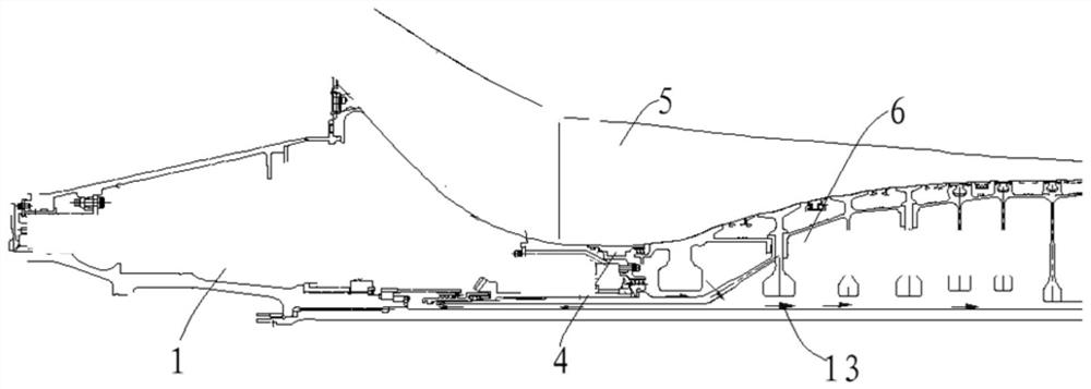
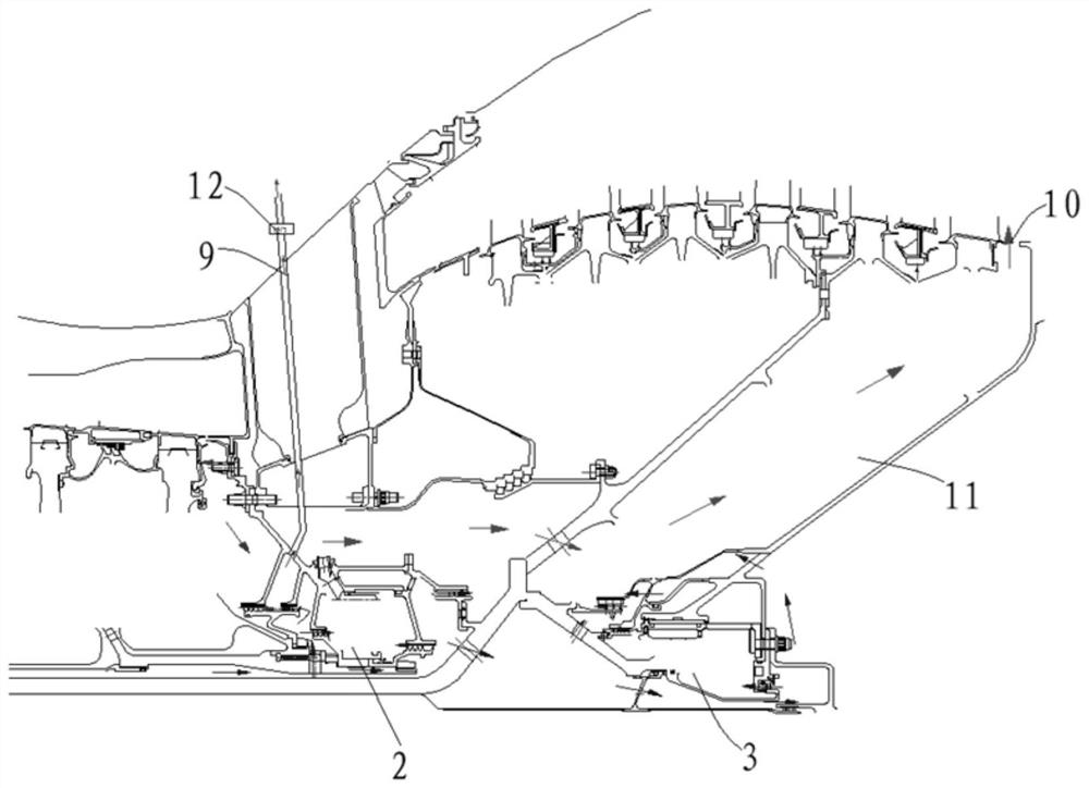
The invention discloses a bearing cavity sealing system of an aero-engine and a control method of the bearing cavity sealing system. The bearing cavity sealing system of the aero-engine comprises an air guide flow path and at least two exhaust flow paths, the air guide flow path is used for guiding sealing air into a middle bearing cavity and a rear bearing cavity from an air compressor, and the exhaust back pressures of the at least two exhaust flow paths are different. The air guide flow path is selectively communicated with at least one exhaust flow path in the at least two exhaust flow paths. According to the bearing cavity sealing system of the aero-engine, the exhaust flow paths with different exhaust back pressures are arranged, so that the exhaust back pressures of the air guide flow paths can be controlled according to the running state of the aero-engine, and then the flow of sealing air is adjusted. When the aero-engine is in a high Mach number pneumatic parameter state, the exhaust back pressure is reduced to further reduce the horizontal distribution of the on-way pressure of an air guide flow path, so that the sealing pressure difference of a bearing cavity is effectively reduced, and the lubricating oil consumption is reduced.

Description

technical field [0001] The invention relates to a bearing cavity sealing system of an aero-engine and a control method thereof. Background technique [0002] In order to ensure the sealing pressure difference of the aero-engine on the ground or in the high-altitude and low Mach number state, it is necessary to introduce the bleed air from the relatively high-level position of the engine compressor, but this will make the aero-engine sealed in the state of high Mach number and high aerodynamic parameters. The differential pressure is large, and an increase in the seal differential pressure risks exceeding the differential pressure limit and increases oil consumption. In order to reduce the risk of seal pressure difference exceeding the limit and reduce the consumption of lubricating oil, the bleed air from the relatively low-level position of the engine compressor is introduced, which will lead to the sealing of the aero-engine in the state of low Mach number aerodynamic para...

Claims


Application Information

Patent Timeline
Patent Type & Authority Applications(China)
IPC IPC(8): F01D25/16F01D11/06F01D25/00
CPCF01D25/16F01D11/06F01D25/00
Inventor 孙平平孙振宇季雁
Owner AECC COMML AIRCRAFT ENGINE CO LTD
Why Eureka
Try Eureka