Air purification device for clean room

An air purification device and clean room technology, applied in the field of air purification, can solve problems such as difficult air, poor air purification effect, drying temperature control, etc.

Pending Publication Date: 2022-04-15
冠恒建设集团有限公司
View PDF5 Cites 0 Cited by
  • Summary
  • Abstract
  • Description
  • Claims
  • Application Information

AI Technical Summary

Problems solved by technology

[0003] The existing air purification device is not effective in purifying the air in the clean room, and it is difficult to dry and control the air temperature. Therefore, the present invention proposes an air purification device for the clean room to solve the above problems

Method used


Image

  • Air purification device for clean room
  • Air purification device for clean room
  • Air purification device for clean room

Examples


Embodiment 1

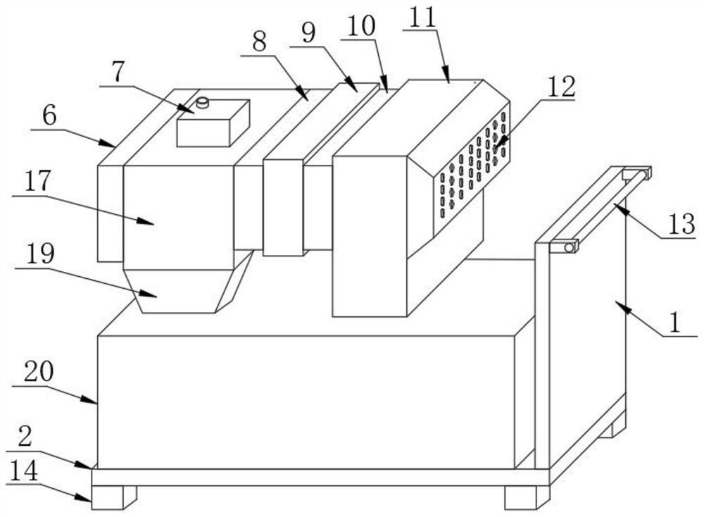
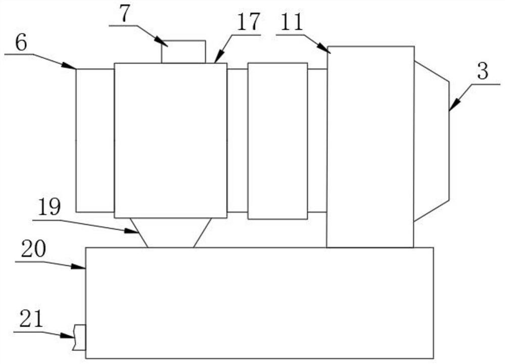
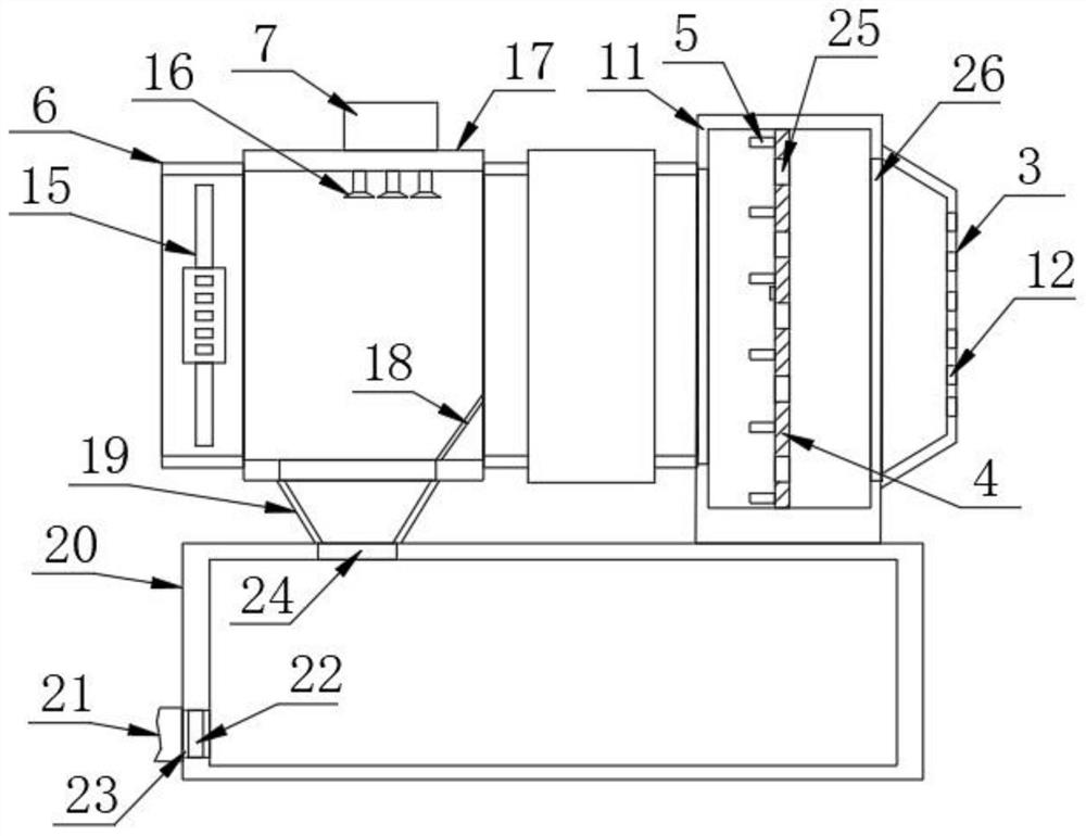
[0026] refer to Figure 1-3 , an air purification device for a clean room, comprising a bottom plate 2, a moving mechanism 14 is fixedly arranged at the four corners of the bottom of the bottom plate 2, and the moving mechanism 14 is adjustable, and a collection box 20 is fixedly arranged on the top of the bottom plate 2, and one side of the collection box 20 is arranged There is a water outlet pipe 21, a first hole 24 is provided on one side of the top of the collection box 20, a water bucket 19 is fixedly arranged on the top of the collection box 20, and a first square pipe 17 is fixedly installed on the top of the water bucket 19, and one side of the first square pipe 17 is fixed A second square pipe 6 is provided, and an exhaust fan 15 is arranged in the second square pipe 6. A water tank 7 is fixedly arranged on the top of the first square pipe 17. A water pump is arranged in the water tank 7. The water pump is connected with an atomizing nozzle 16 through a water pipe. T...

Embodiment 2

[0035] refer to Figure 1-4 , an air purification device for a clean room, comprising a bottom plate 2, a moving mechanism 14 is fixedly arranged at the four corners of the bottom of the bottom plate 2, and the moving mechanism 14 is adjustable, and a collection box 20 is fixedly arranged on the top of the bottom plate 2, and one side of the collection box 20 is arranged There is a water outlet pipe 21, a first hole 24 is provided on one side of the top of the collection box 20, a water bucket 19 is fixedly arranged on the top of the collection box 20, and a first square pipe 17 is fixedly installed on the top of the water bucket 19, and one side of the first square pipe 17 is fixed A second square pipe 6 is provided, and an exhaust fan 15 is arranged in the second square pipe 6. A water tank 7 is fixedly arranged on the top of the first square pipe 17. A water pump is arranged in the water tank 7. The water pump is connected with an atomizing nozzle 16 through a water pipe. T...


PUM


Abstract

The invention discloses an air purification device for a clean room, which comprises a bottom plate, moving mechanisms are fixedly arranged at four corners of the bottom of the bottom plate respectively, a collecting box is fixedly arranged at the top of the bottom plate, a water outlet pipe is arranged on one side of the collecting box, a water bucket is fixedly arranged at the top of the collecting box, and a first square pipe is fixedly arranged at the top of the water bucket; a second square pipe is fixedly arranged on one side of the first square pipe, an exhaust fan is arranged in the second square pipe, a water tank is fixedly arranged at the top of the first square pipe, a water pump is arranged in the water tank and connected with the water pump through a water pipe, and the water pump is located at the top in the first square pipe; a containing box is arranged on the other side of the second square pipe, and second holes are formed in the two sides of the containing box correspondingly; a temperature control mechanism is arranged in the containing box, a T-shaped cover is fixedly arranged on the side wall of the containing box, and a plurality of ventilation holes are formed in the outer wall of the T-shaped cover, and the problems that an existing air purification device is poor in purification effect on air in a clean room, and drying and temperature control are difficult to conduct on air are solved.

Description

technical field [0001] The invention relates to the technical field of air purification, in particular to an air purification device used in a clean room. Background technique [0002] Clean room refers to a well-sealed space that controls air cleanliness, temperature, humidity, pressure, noise and other parameters according to needs. The development of clean rooms is closely related to modern industry and cutting-edge technology. Due to the precision machinery industry (such as gyroscopes, miniature bearings, etc.), the semiconductor industry (such as large-scale integrated circuit production) and other environmental requirements have promoted the development of clean room technology. According to domestic statistics, the qualified rate of producing MOS circuit dies in an environment without cleanliness requirements is only 10% to 15%, and 64 is only 2% for storage. The application of clean room has been quite common. [0003] The existing air purification device is not e...

Claims


Application Information

Patent Timeline
Patent Type & Authority Applications(China)
IPC IPC(8): F24F3/167F24F8/133F24F13/00
CPCF24F3/167F24F8/133F24F13/00F24F2221/34
Inventor 李伟麦尚华
Owner 冠恒建设集团有限公司
Why Eureka
Try Eureka