Combustion pool smoke discharging heat recovery and purification system

A flue gas emission and purification system technology, applied in the direction of combustion methods, water heaters, exhaust gas devices, etc., to achieve the effect of removing soot particles, important economic and environmental benefits

Inactive Publication Date: 2011-09-14
DALIAN UNIV OF TECH
View PDF9 Cites 3 Cited by
  • Summary
  • Abstract
  • Description
  • Claims
  • Application Information

AI Technical Summary

Problems solved by technology

[0004] The technical problem to be solved by the present invention is to solve the problems of waste heat utilization of the flue gas in the combustion pool and the purification and dust removal of the flue gas, so as to solve the problems of low carbon emission, efficient heating, and improvement of the atmospheric environment

Method used


Image

  • Combustion pool smoke discharging heat recovery and purification system
  • Combustion pool smoke discharging heat recovery and purification system
  • Combustion pool smoke discharging heat recovery and purification system

Examples


specific Embodiment approach 1

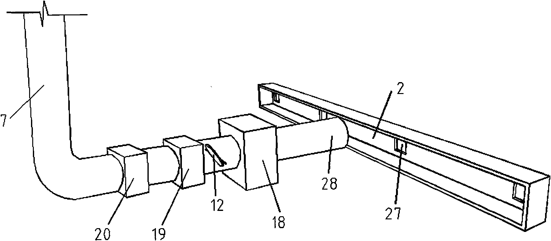
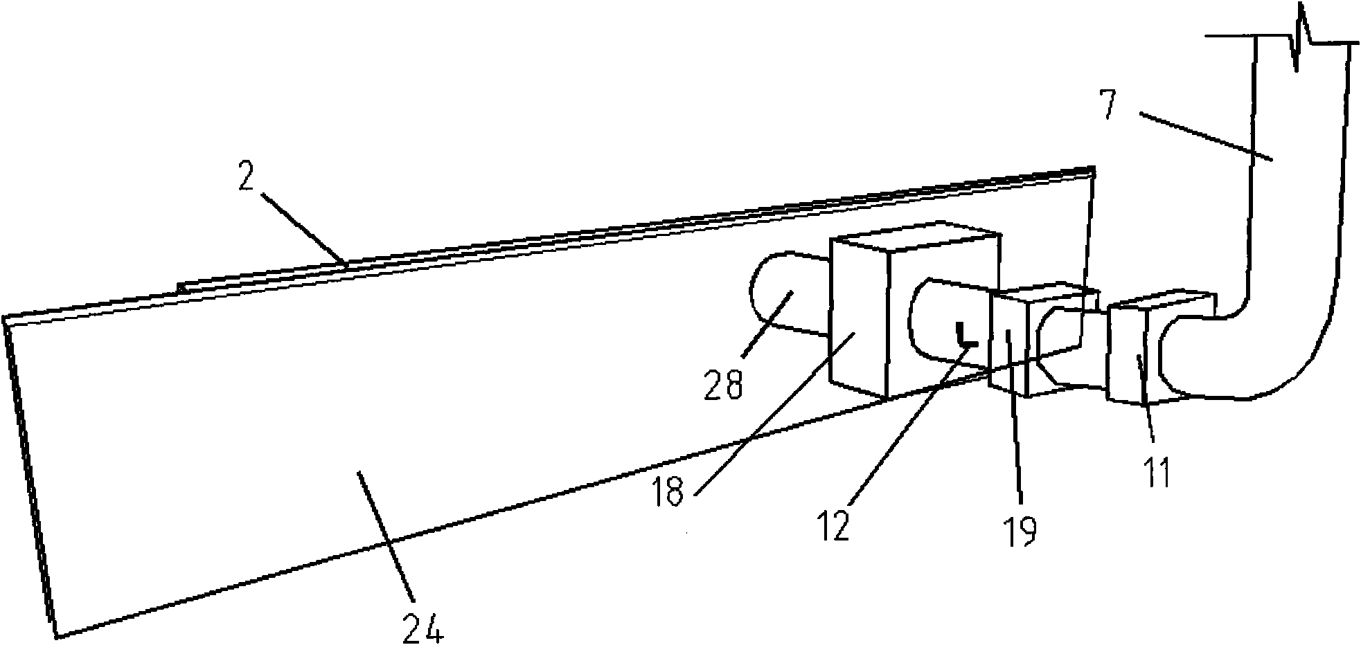
[0013] Specific implementation plan one: if Figure 1~3 As shown, the exhaust heat recovery and purification system of the combustion pool is mainly composed of the combustion pool wall 24, the horizontal flue 2, the chimney 7, the flue gas control valve 12, the flue gas waste heat recovery device 18, the flue gas dust removal device 19, and the flue gas purification The device 20 is composed of other components, which sequentially perform waste heat utilization of flue gas, removal of flue gas particles, and removal of sulfur oxides and nitrogen oxides from flue gas.

specific Embodiment approach 2

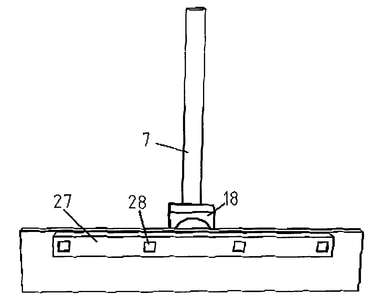
[0014] Specific implementation plan two: if Figure 1~4 As shown, the flue gas waste heat recovery device 18 is located at the chimney inlet 28, and is composed of 21 water pipes, 22 water inlets, and 23 water outlets. After the flue gas passes through the flue opening 27, it is collected at the chimney inlet 28. After entering the flue gas waste heat recovery device 18, it exchanges heat with the water pipe 21, replenishes water through the water inlet 22, and takes the heated water out through the water outlet 23, which is convenient for use.

specific Embodiment approach 3

[0015] Specific implementation plan three: if Figure 2~4 As shown, the flue system is composed of a horizontal flue 2 , several flue openings 27 , a flue gas purification device 11 , and a vertical chimney 7 . The horizontal flue 2 is located at the back of the combustion pool wall 24 and consists of four symmetrical flue openings 27 . The flue gas is collected by the flue opening 27 and collected at the horizontal flue 2. The flue gas passes through the flue gas waste heat recovery device 18, the flue gas dust removal device 19, and the flue gas purification device 20 for purification and dust removal, and finally is discharged from the chimney 7. A flue gas control valve 12 is also provided at the bottom of the chimney, and the smoke exhaust volume is controlled by changing the angle of the flue gas control valve 12 .


PUM


Abstract

The invention relates to a combustion pool smoke discharging heat recovery and purification system, belonging to the technical field of recycle of resources and building energy conservation. The system is characterized by mainly consisting of a horizontal flue, flue ports, a vertical chimney, a smoke control valve, a smoke residual heat recovery device, a smoke dust collection device and a smoke purification device; the horizontal flue is provided with a plurality of the flue ports to collect smoke; and the smoke is sequentially subjected to smoke residual heat recycle, smoke particle desorption, and removal of harmful gases such as sulfur oxide, nitrogen oxide in the smoke through the smoke residual heat recovery device, the smoke dust collection device and the smoke purification device, and finally the smoke is discharged through the vertical chimney. The system provided by the invention has the beneficial effects of smoke purification, low carbon discharging, efficient heating, outdoor environmental improvement and the like, can be used in dwelling houses in villages and small towns and industrial factory buildings without central heating, and has very important promotional value and obvious environmental and economic benefits.

Description

technical field [0001] The invention belongs to the technical field of resource reuse and building energy saving, and relates to a heat recovery and purification system for flue gas exhaust from a combustion pool. Background technique [0002] In the rural areas of our country, waste biomass materials such as straw, corncobs, dead branches and leaves, and coal are used as fuel for heating in winter. When the fuel is burned, a large amount of sulfur dioxide, nitrogen dioxide, and inhalable particulate matter will be released into the atmosphere, causing serious pollution. Indoor and outdoor environments can cause harm to human health. In my country, the rural population accounts for more than 70% of the total population, and the proportion of underdeveloped areas and population is still relatively large. Due to the insufficient waste heat and purification treatment of flue gas in the process of production and life, respiratory diseases in rural areas are still a common proble...

Claims


Application Information

Patent Timeline
Patent Type & Authority Applications(China)
IPC IPC(8): F23J11/00F23J15/02F24H1/00
Inventor 陈滨刘鸣张宝刚张雪妍朱佳音田维治谢艺强白淑鑫张瑞娜
Owner DALIAN UNIV OF TECH
Why Eureka
Try Eureka