
Rotary cutting tool and cutting tool portion

A cutting tool and tool technology, applied in the field of cutting tool base and cutting tip, can solve the problem of easy assembly and disassembly target conflict

Pending Publication Date: 2022-04-19
KENNAMETAL INC
View PDF0 Cites 0 Cited by
  • Summary
  • Abstract
  • Description
  • Claims
  • Application Information

AI Technical Summary

Problems solved by technology

[0009] Obviously there is some conflicting goals between being easy to assemble and disassemble and keeping the parts together securely

Method used


Image

  • Rotary cutting tool and cutting tool portion
  • Rotary cutting tool and cutting tool portion
  • Rotary cutting tool and cutting tool portion

Examples


Embodiment Construction

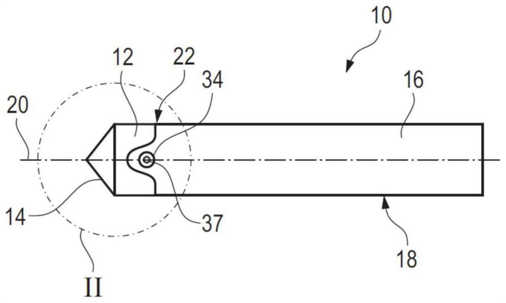
[0039] figure 1 A rotary cutting tool 10 is shown, which in the illustrated embodiment is a drill.

[0040] The rotary cutting tool 10 includes a first cutting tool portion 12 on which a cutting edge 14 is disposed. Accordingly, the first cutting tool part 12 may also be referred to as a cutting tip.

[0041] The rotary cutting tool 10 also includes a second cutting tool portion 16 that includes a cutting tool shank 18 . In simplified form, the second cutting tool portion 16 may thus be referred to as a cutting tool base or cutting tool shank.

[0042] The first cutting tool part 12 and the second cutting tool part 16 are disposed adjacent to each other along the axis of rotation 20 of the rotary cutting tool 10 and are releasably connected to each other via a coupling mechanism 22 .

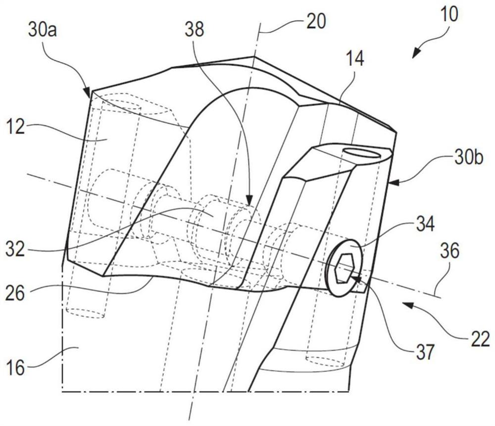
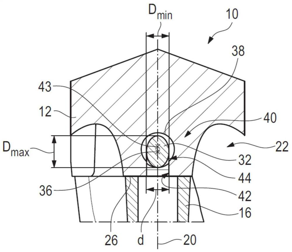
[0043] Reference below Figures 2 to 7 The coupling mechanism 22 is discussed in more detail.

[0044] In this regard, the second cutting tool part 16 includes a coupling interface 24 for c...


PUM


Abstract

The invention discloses a rotary cutting tool and a cutting tool portion. A rotary cutting tool (10), in particular a drill, comprises a first cutting tool portion (12) having at least one cutting edge (14) and a second cutting tool portion (16) comprising a cutting tool shank. The first cutting tool part (12) and the second cutting tool part (16) are releasably connected to each other via a coupling mechanism (22) comprising a coupling cam (32) mounted on one of the two cutting tool parts (12, 16), the coupling cam is rotatable about an axis of rotation (36) and adjoins an engagement surface (38) on the other cutting tool portion (12, 16) in a coupled position. The invention also provides a cutting tool part (16), in particular a cutting tool base, and a further cutting tool part (12), in particular a cutting tip.

Description

technical field [0001] The invention relates to a rotary cutting tool, in particular a drill, comprising a first cutting tool part on which at least one cutting edge is arranged and a second cutting tool part comprising a cutting tool shank. The first cutting tool part and the second cutting tool part are adjacent to each other along an axis of rotation of the rotary cutting tool and are releasably connected to each other via a coupling mechanism. [0002] The invention also relates to a cutting tool part for such a rotary cutting tool, in particular a cutting tool base comprising a coupling interface for coupling the cutting tool part to another cutting tool part. Such cutting tool parts are also sometimes referred to as cutting tool shanks, which is an oversimplification given the fact that they include more than just cutting tool shanks. [0003] The invention also relates to a further cutting tool part, in particular a cutting tip, for such a rotary cutting tool, comprisi...

Claims


Application Information

Patent Timeline
Patent Type & Authority Applications(China)
IPC IPC(8): B23B51/00
CPCB23B51/00B23B51/0003B23B2260/02
Inventor S.M.欧里庇得斯C.盖伊P.库赫莱曼
Owner KENNAMETAL INC
Learn More