A small dredging device with hydropower dual energy supply

A dredging device and energy supply technology, which is applied in mechanically driven excavators/dredgers, construction, earthmoving machines/shovels, etc. problems such as poor effect, to achieve the effect of facilitating later transportation, improving the dredging effect, and reducing the moisture content

Active Publication Date: 2022-05-06
NORTH CHINA UNIV OF WATER RESOURCES & ELECTRIC POWER
View PDF5 Cites 0 Cited by
  • Summary
  • Abstract
  • Description
  • Claims
  • Application Information

AI Technical Summary

Problems solved by technology

[0005] Aiming at the current defects and problems of long dredging time, low dredging efficiency, high cost of large dredging equipment, great impact of dredging or poor dredging effect, the present invention provides a small dredging device with dual power supply of hydropower

Method used


Image

  • A small dredging device with hydropower dual energy supply
  • A small dredging device with hydropower dual energy supply
  • A small dredging device with hydropower dual energy supply

Examples


Embodiment 1

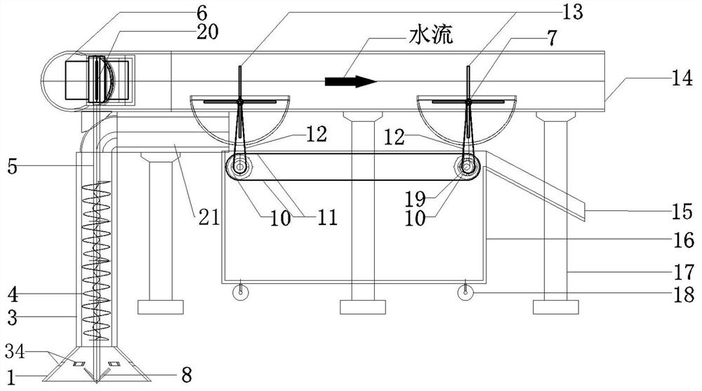
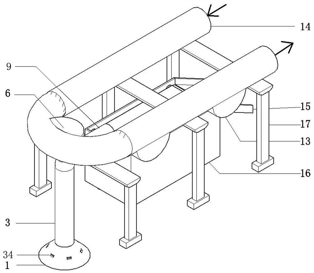
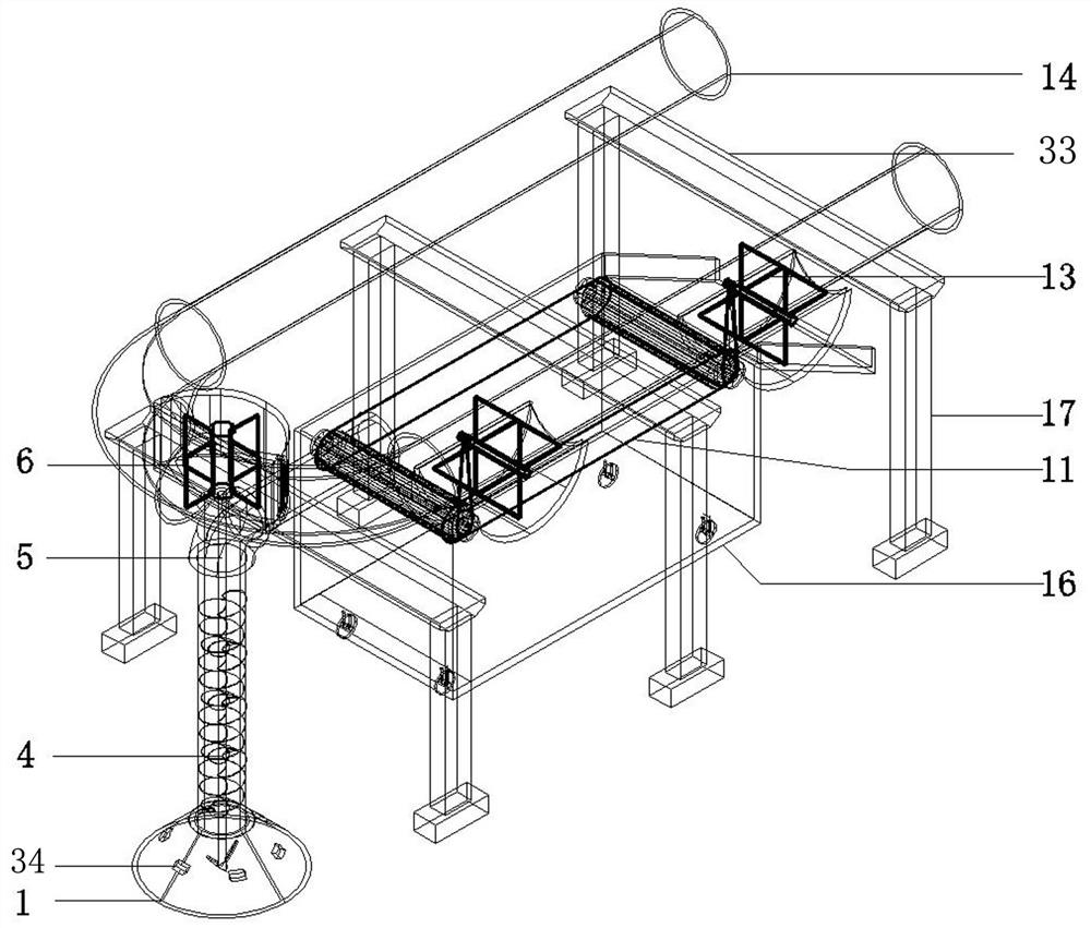
[0027] Embodiment 1: This embodiment provides a small-scale dredging device with dual power supply of water and electricity, such as Figure 1-4 As shown, the small dredging device includes a fixed bracket 17, a water delivery pipeline 2, a silt suction mechanism and a sludge treatment mechanism, the water delivery pipeline 2 is provided with a water collection box 16, the bottom of the water collection box is provided with a drain outlet, and the bottom is provided with Roller 18; Wherein fixed bracket comprises support leg 32 and lateral support plate 33, and water pipeline is U-shaped pipeline, and it is horizontally placed on the horizontal support plate 33 of fixed bracket 17; Water pipeline 2 comprises three parts, is water inlet pipe respectively 29. The connecting pipe 30 and the outlet pipe 31. The connecting pipe 30 is the front end of the entire water delivery pipe 2. A vertical water wheel installation cavity 22 is provided in the middle of the connecting pipe 30. T...

Embodiment 2

[0033] Embodiment 2: The similarities between this embodiment and Embodiment 1 will not be repeated, and the difference is that, as Figure 5 As shown, in order to further ensure the silt suction effect of the silt suction mechanism, a drive gear 24 with a small wheel diameter is provided under the rotating shaft 20 of the vertical impeller 6, and a driven gear 25 with a large wheel diameter is meshed on the side of the drive gear. The transmission shaft 5 is coaxially connected with the driven gear 25, and the transmission ratio of the driving gear and the driven gear is controlled between 1:5-1:10. When the vertical water wheel 6 is impacted and rotated by the water flow, the driving gear of the small wheel diameter drives the driven gear of the large wheel diameter to drive the transmission shaft to rotate, which can increase the agitation force of the transmission shaft, enhance the agitation effect of the transmission shaft, and ensure the suction The silt in the mud hopp...


PUM


Abstract

The invention belongs to the technical field of dredging equipment, and in particular relates to a small dredging device with dual power supplies of water and electricity. The desilting device impacts the vertical impeller through the water flow with natural potential energy or the water supplied by the water pump to drive the transmission shaft to stir up the sludge and transfer the sludge to the sludge conveyor belt. The water flow hits the front and rear two horizontal impellers, and the horizontal impeller rotates through the belt Drive the movement of the sludge conveyor belt so that the sludge is transported to the sludge conveyor belt and discharged from the discharge hopper; the suction bucket of the device directly penetrates into the sludge, and it is not easy to disturb the upper clarified water layer during the dredging process, which has little or no influence on the upper clear water. It can realize non-stop water dredging; it can pretreat the cleaned sludge, reduce the moisture content of the sludge, and facilitate later transportation; it can realize the role of separate or coordinated energy supply of electric energy and water energy, saving energy, and the overall structure is simple. Small size, suitable for small dredging sites, and better for circular funnel bottom dredging.

Description

technical field [0001] The invention belongs to the technical field of dredging equipment, and in particular relates to a small dredging device with dual power supplies of water and electricity. Background technique [0002] With the development of the economy, urbanization is advancing by leaps and bounds, the urban population is gradually increasing, and the discharge of domestic garbage and sewage is gradually increasing, resulting in a gradual increase in the discharge of sludge. According to statistics, about 25 million tons of dry sludge are produced in my country every year. And it is still growing at a rate of 10% every year, and the amount of silt is huge. [0003] In the process of ecological civilization construction, a series of water environment management problems have been highlighted. It is urgent to change from "heavy water and light mud" to "equal emphasis on mud and water", and from "sewage treatment" to "recycling". Treatment and resource utilization have...

Claims


Application Information

Patent Timeline
Patent Type & Authority Patents(China)
IPC IPC(8): E02F3/88E02F5/28
CPCE02F3/88E02F5/28
Inventor 钟凌郭利霞郭磊汪伦焰陈平平李松
Owner NORTH CHINA UNIV OF WATER RESOURCES & ELECTRIC POWER
Why Eureka
Try Eureka