Signal analysis of movement of reference electrode of catheter in coronary sinus vein

A catheter and electrode technology, applied in the field of signal processing, can solve problems such as improving the stability of electrodes/catheters

Pending Publication Date: 2022-04-22
伯恩森斯韦伯斯特(以色列)有限责任公司
0 Cites 0 Cited by

AI-Extracted Technical Summary

Problems solved by technology

[0004] No technology currently exists to improve ele...

Method used

[0071] Turning now to FIG. 3, a method 300 (eg, performed by the device orientation engine 101 of FIG. 1 and/or FIG. 2) is shown, according to one or more embodiments. Method 300 addresses the need for reliable measurement and mapping by providing multi-step signal analysis of electrical signals representing movement of a reference electrode of catheter 110 in a CS vein, which enables improved understanding of electrophysiology with greater precision. In this example, catheter 110 is a linear catheter with a plurality of electrodes 111 . Multiple electrodes 111 of catheter 110 may be grouped (such as paired) and may provide positional information over time.
[0095] Method 600 addresses the need to understand and visualize whether a reference electrode within the CS (eg, a reference e...

Abstract

The invention relates to signal analysis of movement of a reference electrode of a catheter in a coronary sinus vein. A method is provided. The method is implemented by a device orientation engine executed by one or more processors. The method includes determining movement between each electrode set of the catheter to provide movement, and determining a total movement of the electrodes of the catheter. The method also includes removing a standard component from the movement and the total movement, and outputting a movement indication of the catheter based on the movement and the total movement using the standard component.

Application Domain

Surgical navigation systemsDiagnostic recording/measuring +1

Technology Topic

Biomedical engineeringVein +3

Image

  • Signal analysis of movement of reference electrode of catheter in coronary sinus vein
  • Signal analysis of movement of reference electrode of catheter in coronary sinus vein
  • Signal analysis of movement of reference electrode of catheter in coronary sinus vein

Examples

  • Experimental program(1)

Example Embodiment

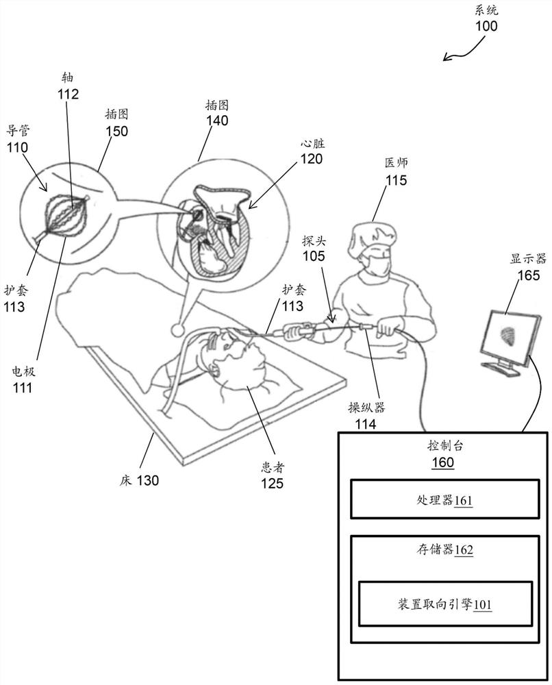
[0020] A method and system for signal processing are disclosed herein. More specifically, the present invention relates to signal analysis of movement of a reference electrode of a catheter in a coronary sinus (CS) vein.
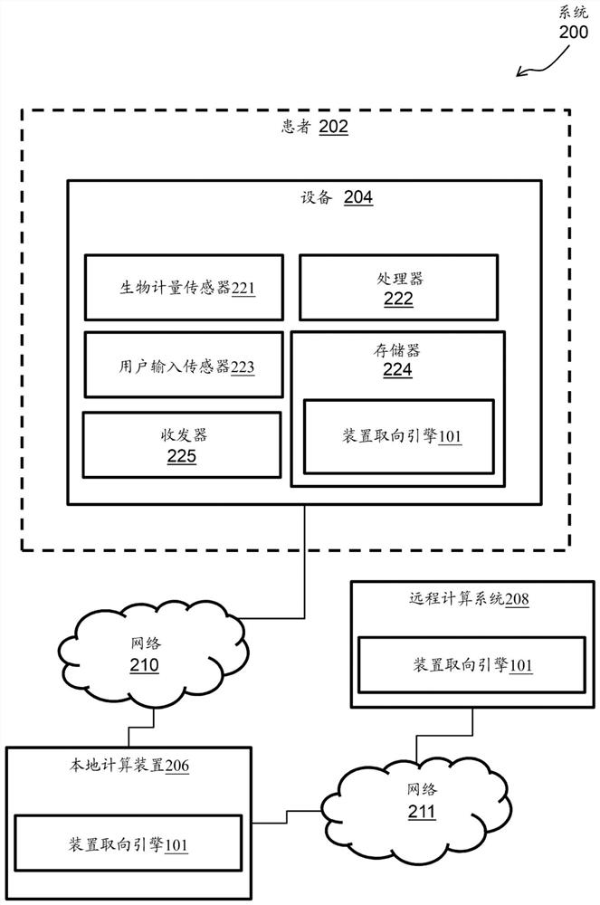
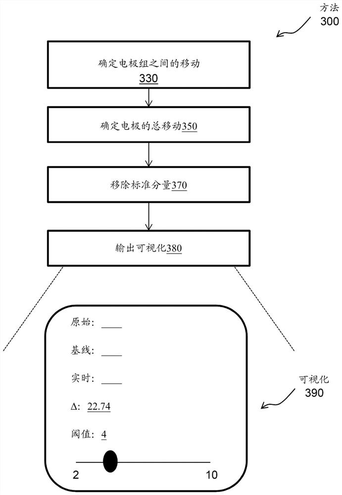
[0021] For example, a device-oriented engine is processor-executable code or software that must be rooted in the process operations performed by the medical device device as well as in the processing hardware of the medical device device. According to an exemplary embodiment, the device orientation engine may include a machine learning/artificial intelligence (ML/AI) algorithm. The device orientation engine tracks the movement of the CS catheter within the CS while mapping the CS. For example, the device orientation engine tracks the movement of the CS catheter along the axial axis of the CS (which can affect the stability of the map's reference), and tracks deviations from the acquired reference position at the beginning of the mapping.
[0022] Technical effects and benefits of the device orientation engine include providing cardiologists and medical personnel with a visual representation of the original catheter position relative to the displaced catheter position following inadvertent catheter movement. Thus, the device orientation engine utilizes and transforms medical device equipment among other things to enable/enable CS catheter displacement estimation that is not currently available or currently performed by cardiac electrophysiological systems.
[0023] According to one or more implementations, a device orientation engine executed by one or more processors implements a method. The method includes determining movement between each set of electrodes of the catheter to provide movement, and determining a total movement of the electrodes of the catheter. The method also includes removing a standard component from the movement and the total movement, and outputting an indication of movement of the catheter based on the movement and the total movement using the standard component.
[0024] According to one or more embodiments herein or any method embodiment, the device orientation engine may utilize as input the position of each time stamp and the reference position of the electrodes of each electrode set for use in determining the distance between each electrode set. move.
[0025] According to one or more embodiments herein or any method embodiment, movement between each electrode set may be determined based on at least one set of two vectors constructed for each electrode set.
[0026] According to one or more embodiments or any method embodiments herein, movement between each electrode set may be determined based on a third vector between the set of two vectors for each electrode set.
[0027] According to one or more embodiments herein or any method embodiment, the total movement may be based on the average movement of the three intermediate electrode pairs of the plurality of electrodes.
[0028] According to one or more embodiments herein or any method embodiment, the processor-executable code may be further executed to cause the system to determine a median value for each movement between each electrode pair; selecting the closest to the median value three moving the measurements to provide the selected measurement; and determining an average of the selected measurements to provide the average shift.
[0029] According to one or more embodiments herein, or any method embodiment, the standard component may include respiratory motion or heartbeat motion.
[0030] According to one or more embodiments herein or any method implementation, the indication of movement may be for each input position compared to a reference position.
[0031] According to one or more embodiments herein or any method embodiment, the indication of movement may be along the axis of axial insertion of the catheter into the coronary sinus.
[0032] According to one or more embodiments, a system includes a memory and one or more processors. The memory stores processor executable code for the device orientation engine. The one or more processors execute the processor-executable code to cause the system and the device orientation engine to determine movement between each set of electrodes of the catheter to provide movement and determine a total movement of the electrodes of the catheter. The processor-executable code further causes the system and the device orientation engine to remove a normative component from the movement and the total movement, and to output an indication of movement of the catheter based on the movement and the total movement using the normative component.
[0033] According to one or more embodiments herein or any system embodiment, the device orientation engine may utilize as input the position of each time stamp and the reference position of the electrodes of each electrode set for use in determining the distance between each electrode set. move.
[0034] According to one or more embodiments herein, or any system implementation, movement between each electrode set may be determined based on at least one set of two vectors constructed for each electrode set.
[0035] According to one or more embodiments herein or any system implementation, movement between each electrode set may be determined based on a third vector between the set of two vectors for each electrode set.
[0036] According to one or more embodiments herein or any system implementation, the total movement may be based on the average movement of the three intermediate electrode pairs of the plurality of electrodes.
[0037] According to one or more embodiments herein or any system implementation, the processor-executable code can be further executed to cause the system to determine a median value for each movement between each electrode pair; select the closest three moving the measurements to provide the selected measurement; and determining an average of the selected measurements to provide the average shift.
[0038] According to one or more embodiments herein, or any system embodiment, the standard component may include respiratory motion or heartbeat motion.
[0039] According to one or more embodiments herein, or any system implementation, the indication of movement may be for each input position compared to a reference position.
[0040] According to one or more embodiments herein, or any system embodiment, the indication of movement may be along the axis of axial insertion of the catheter into the coronary sinus.
[0041] According to one or more embodiments herein, or any system embodiment, the conduit may be a linear conduit.
[0042] figure 1 Is an illustration of a system 100 (eg, a medical device apparatus) that can implement one or more features of the subject matter herein, according to one or more embodiments. All or part of system 100 may be used to collect information (eg, biometric data and/or training data sets) and/or to implement device orientation engine 101 , as described herein.
[0043]As shown, system 100 includes probe 105 having catheter 110 (including at least one electrode 111 ), shaft 112 , sheath 113 and manipulator 114 . As shown, system 100 also includes physician 115 (or medical professional, clinician, technician, etc.), heart 120, patient 125, and bed 130 (or table). Note that insets 140 and 150 show heart 120 and catheter 110 in greater detail. As shown, system 100 also includes a console 160 (including one or more processors 161 and memory 162 ) and a display 165 . Note also that each element and/or item of system 100 represents one or more of that element and/or that item. figure 1 The illustrated example of system 100 may be modified to implement the embodiments disclosed herein. The disclosed embodiments of the present invention are similarly applicable using other system components and arrangements. Additionally, the system 100 may include additional components, such as elements for sensing electrical activity, wired or wireless connectors, processing and display devices, and the like.
[0044] System 100 may be used to detect, diagnose, and/or treat cardiac disorders (eg, using device orientation engine 101 ). Cardiac disorders such as cardiac arrhythmias remain common and dangerous medical conditions, especially in the elderly. Additionally, system 100 may be a surgical system (e.g., the Biosense Webster® marketed by Biosense Webster system) configured to obtain biometric data (eg, anatomical and electrical measurements of a patient's organ, such as the heart 120 ) and perform cardiac ablation procedures.
[0045] In a patient (eg, patient 125) with normal sinus rhythm (NSR), the heart (eg, heart 120 ), including the atria, ventricles, and excitatory conduction tissue, is electrically stimulated to beat in a synchronized, patterned manner. Note that this electrical excitation may be detected as intracardiac electrogram (IC ECG) data or the like.
[0046] In patients (eg, Patient 125) with cardiac arrhythmias (eg, atrial fibrillation or aFib), abnormal areas of cardiac tissue do not follow the synchronized beating cycles associated with normally conducting tissue, which develops in patients with NSR Compared. Instead, abnormal areas of cardiac tissue conduct abnormally to adjacent tissue, disrupting the cardiac cycle into an asynchronous rhythm. Note that this asynchronous rhythm can also be detected as IC ECG data. This abnormal conduction was previously known to occur in various regions of the heart 120, such as in the region of the sinoatrial (SA) node, along the conduction pathways of the atrioventricular (AV) node, or in the myocardial tissue that forms the walls of the ventricles and atrial heart chambers .
[0047] To support system 100 in detecting, diagnosing, and/or treating a cardiac disorder, probe 105 may be navigated by physician 115 into heart 120 of patient 125 lying on bed 130 . For example, physician 115 may insert shaft 112 through sheath 113 while manipulating the distal end of shaft 112 using manipulator 114 near the proximal end of catheter 110 and/or deflecting from sheath 113 . As shown in inset 140 , basket catheter 110 may fit at the distal end of shaft 112 . Basket catheter 110 may be inserted through sheath 113 in a collapsed state and may then be deployed within heart 120 .
[0048] Catheter 110, which may include at least one electrode 111 and a catheter needle coupled to its body, may be configured to obtain biometric data, such as electrical signals of internal organs (e.g., heart 120), and/or ablate regions of tissue thereof (e.g., heart 120). cardiac chambers of the heart 120). Note that electrodes 111 represent any similar element, such as a tracking coil, piezoelectric transducer, electrode, or combination of elements configured to ablate a tissue region or obtain biometric data. According to one or more embodiments, catheter 110 may include one or more position sensors for determining trajectory information. Trajectory information can be used to infer motion properties, such as tissue contractility.
[0049] Biometric data (e.g., patient biometrics, patient data, or patient biometric data) may include one or more of local activation time (LAT), electrical activity, topology, bipolar mapping, dominant frequency, impedance, etc. . The LAT may be the time point of threshold activity corresponding to local activation calculated based on a normalized initial starting point. Electrical activity can be any applicable electrical signal that can be measured based on one or more thresholds and that can be sensed and/or enhanced based on a signal-to-noise ratio and/or other filters. A topology may correspond to the physical structure of a body part or a portion of a body part, and may correspond to a variation of the physical structure with respect to different parts of the body part or with respect to different body parts. A dominant frequency may be a frequency or frequency range that is prevalent at a part of a body part, and may be different in different parts of the same body part. For example, the dominant frequency of the PV of a heart may be different than the dominant frequency of the right atrium of the same heart. Impedance may be a measurement of electrical resistance at a given area of ​​a body part.
[0050] Examples of biometric data include, but are not limited to, patient identification data, IC ECG data, anatomical and electrical measurements, trajectory information, body surface (BS) ECG data, historical data, brain biometrics, blood pressure data, ultrasound signals, radio signals , audio signals, two-dimensional or three-dimensional image data, blood glucose data and temperature data. Biometric data can generally be used to monitor, diagnose, and treat any number of various diseases, such as cardiovascular disease (e.g., arrhythmia, cardiomyopathy, and coronary artery disease) and autoimmune disease (e.g., type I and II type diabetes). Note that BS ECG data may include data and signals collected from electrodes on the patient's surface, IC ECG data may include data and signals collected from electrodes inside the patient, and ablation data may include data collected from tissue that has been ablated and signal. Additionally, BS ECG data, IC ECG data, and ablation data along with catheter electrode position data may be derived from one or more procedure records.
[0051] For example, catheter 110 may use electrodes 111 to enable intravascular ultrasound and/or MRI catheterization to image heart 120 (eg, obtain and process biometric data). Inset 150 shows catheter 110 within a cardiac chamber of heart 120 in an enlarged view. While catheter 110 is shown as a pointed catheter, it should be understood that any shape including one or more electrodes 111 may be used to implement the embodiments disclosed herein.
[0052] Examples of catheter 106 include, but are not limited to, a linear catheter with multiple electrodes, a balloon catheter including electrodes dispersed over multiple ridges that shape the balloon, a noose or loop catheter with multiple electrodes, or any other suitable shape. The linear catheter can be fully or partially elastic such that it can twist, bend and/or otherwise change its shape based on received signals and/or based on exerting external forces (eg, heart tissue) on the linear catheter. The balloon catheter can be designed such that when deployed in a patient, its electrodes can be held in tight contact against the endocardial surface. For example, a balloon catheter can be inserted into a lumen such as a pulmonary vein (PV). The balloon catheter can be inserted into the PV in a deflated state such that the balloon catheter does not occupy its largest volume when inserted into the PV. The balloon catheter can be inflated inside the PV such that those electrodes on the balloon catheter are in contact with the entire circular segment of the PV. Such access to the entire circular segment of the PV, or any other lumen, enables efficient imaging and/or ablation.
[0053] Probe 105 and other items of system 100 may be connected to console 160 . Console 160 may include any computing device that can employ the ML/AI algorithms of device-oriented engine 101 . According to one embodiment, console 160 includes one or more processors 161 (any computing hardware) and memory 162 (any non-transitory tangible medium), wherein one or more processors 161 execute computer instructions for device orientation engine 101 , and the memory 162 stores these instructions for execution by the one or more processors 161. For example, console 160 may be configured to receive and process biometric data and determine whether a given tissue region is conductive. In some embodiments, the console 160 can also be programmed (in software) by the device orientation engine 101 to perform the following functions: determine the movement between each electrode set of the catheter to provide movement; determine the total movement of the electrodes of the catheter; removing a standard component from the movement and the total movement; and outputting an indication of movement of the catheter based on the movement and the total movement using the standard component. According to one or more embodiments, the device orientation engine 101 may be located external to the console 160, and may be located, for example, in the catheter 110, in an external device, in a mobile device, in a cloud-based device, or may be a separate processor. In this regard, the device orientation engine 101 may be transmitted/downloaded in electronic form over a network.
[0054] In an example, console 160 may be any computing device (such as a general-purpose computer) as described herein including software (e.g., device orientation engine 101) and/or hardware (e.g., processor 161 and memory 162), which has Suitable front-end and interface circuitry for transmitting signals to and receiving signals from the probe 105 and for controlling other components of the system 100 . For example, the front-end and interface circuitry includes an input/output (I/O) communication interface that enables console 160 to receive signals from at least one electrode 111 and/or transmit signals to at least one electrode 111. electrode. Console 160 may include real-time noise reduction circuitry typically configured as a field programmable gate array (FPGA), followed by an analog-to-digital (A/D) ECG or electrocardiograph or electromyography (EMG) signal conversion integrated circuit. Console 160 may pass signals from the A/DECG or EMG circuitry to another processor and/or may be programmed to perform one or more functions disclosed herein.
[0055] Display 165 , which may be any electronic device for visual presentation of biometric data, is connected to console 160 . According to one embodiment, during a procedure, console 160 may facilitate presenting a body part rendering to physician 115 on display 165 and store data representative of the body part rendering in memory 162 . For example, a map characterizing motion may be rendered/constructed based on trajectory information sampled at a sufficient number of points in the heart 120 . As an example, display 165 may include a touch screen that may be configured to accept input from physician 115 in addition to presenting body part renderings.
[0056] In some embodiments, physician 115 may use one or more input devices (such as a touchpad, mouse, keyboard, gesture recognition device, etc.) to manipulate elements of system 100 and/or body part renderings. For example, an input device may be used to change the position of catheter 110 such that the rendering is updated. Note that the display 165 may be located at the same location or at a remote location, such as in a separate hospital or a separate healthcare provider network.
[0057] According to one or more embodiments, system 100 may also obtain biometric data using ultrasound, computed tomography (CT), MRI, or other medical imaging techniques using catheter 110 or other medical equipment. For example, system 100 may use one or more catheters 110 or other sensors to obtain ECG data and/or anatomical and electrical measurements (eg, biometric data) of heart 120 . More specifically, console 160 may be connected by cables to BS electrodes comprising adhesive skin patches attached to patient 125 . The BS electrodes can acquire/generate biometric data in the form of BS ECG data. For example, processor 161 may determine location coordinates of catheter 110 within a body part of patient 125 (eg, heart 120 ). These position coordinates may be based on impedance or electromagnetic fields measured between the body surface electrodes and the electrodes 111 or other electromagnetic components of the catheter 110 . Additionally or alternatively, a place mat can be located on the surface of the bed 130 and can be separated from the bed 130 . Biometric data may be transmitted to console 160 and stored in memory 162 . Alternatively or in addition, the biometric data may be transmitted to a server, which may be local or remote, using a network as otherwise described herein.
[0058]According to one or more embodiments, catheter 110 may be configured to ablate tissue regions of cardiac chambers of heart 120 . Inset 150 shows catheter 110 within a cardiac chamber of heart 120 in an enlarged view. For example, an ablation electrode such as at least one electrode 111 may be configured to provide energy to a tissue region of an internal organ (eg, heart 120). The energy may be thermal energy and may cause damage to the tissue region starting at the surface of the tissue region and extending into the thickness of the tissue region. Biometric data relative to an ablation protocol (eg, ablated tissue, ablated location, etc.) may be considered ablation data.
[0059] now go to figure 2 , shows a diagram of a system 200 in which one or more features of the disclosed subject matter may be implemented, according to one or more implementations. With respect to patient 202 (for example, figure 1 example of patient 125 ), system 200 includes device 204 , local computing device 206 , remote computing system 208 , first network 210 and second network 211 . Additionally, device 204 may include a biometric sensor 221 (eg, figure 1 example of catheter 110 ), processor 222 , user input (UI) sensor 223 , memory 224 and transceiver 225 . Note that for ease of explanation and brevity, figure 1 The device orientation engine 101 in the figure 2 is reused in .
[0060] According to one embodiment, device 204 may be figure 1 An example of the system 100 in which the device 204 can include both components inside the patient and components outside the patient. According to one embodiment, device 204 may be a device external to patient 202 that includes an attachable patch (eg, attached to the patient's skin). According to another embodiment, the device 204 may be inside the body of the patient 202 (eg, implanted subcutaneously), wherein the device 204 may be inserted into the patient 202 via any suitable means, including oral injection, surgical insertion via a vein or artery, internal Endoscopic or laparoscopic procedures. According to one embodiment, although in figure 2 A single device 204 is shown in , but an exemplary system may include multiple devices.
[0061] Accordingly, device 204 , local computing device 206 and/or remote computing system 208 may be programmed to execute computer instructions with respect to device orientation engine 101 . For example, memory 224 stores these instructions for execution by processor 222 such that device 204 may receive and process biometric data via biometric sensor 201 . As such, processor 222 and memory 224 represent the processor and memory of local computing device 206 and/or remote computing system 208 .
[0062] Device 204, local computing device 206 and/or remote computing system 208 may be any combination of software and/or hardware that individually or collectively store, execute and implement device orientation engine 101 and its functions. Additionally, device 204, local computing device 206, and/or remote computing system 208 may be an electronic computer framework including and/or employing any number and combination of computing devices and networks utilizing various communication technologies, as described herein. Appliance 204, local computing device 206, and/or remote computing system 208 can be easily scaled, expanded, and modularized, with the ability to change for different services or reconfigure some features independently of other features.
[0063] Networks 210 and 211 may be wired networks, wireless networks, or include one or more wired and wireless networks. According to one embodiment, network 210 is an example of a short-range network such as a local area network (LAN) or a personal area network (PAN). Any of a variety of short-range wireless communication protocols, such as Bluetooth, Wi-Fi, Zigbee, Z-Wave, near-field communication (NFC), ultra-band, Zigbee, or infrared (IR), can be used to communicate over the network 210. Information is sent between device 204 and local computing device 206 . Additionally, network 211 is an example of one or more of: an intranet, a local area network (LAN), a wide area network (WAN), a metropolitan area network (MAN), a direct connection or series of connections, a cellular telephone network, or is capable of facilitating Any other network or medium of communication between the local computing device 206 and the remote computing system 208 . Information may be sent via network 211 using any of a variety of long-range wireless communication protocols (eg, TCP/IP, HTTP, 3G, 4G/LTE, or 5G/New Radio). Note that for either of the networks 210 and 211, a wired connection may be implemented using Ethernet, Universal Serial Bus (USB), RJ-11, or any other wired and wireless connection may use Wi-Fi, WiMAX , and Bluetooth, infrared, cellular, satellite, or any other wireless connection method.
[0064] In operation, device 204 may continuously or periodically obtain, monitor, store, process, and communicate biometric data associated with patient 202 via network 210 . Additionally, device 204, local computing device 206, and/or remote computing system 208 communicate over networks 210 and 211 (eg, local computing device 206 may be configured as a gateway between device 204 and remote computing system 208). For example, device 204 may be figure 1 An example of a system 100 configured to communicate with a local computing device 206 via a network 210 . Local computing device 206 may be, for example, a fixed/standalone device, base station, desktop/laptop computer, smart phone, smart watch, tablet, or other device configured to communicate with other devices via networks 211 and 210 . Implemented as physical servers on or connected to the network 211 or a public cloud computing provider of the network 211 (e.g., Amazon Web Services The remote computing system 208 of the virtual server in ) can be configured to communicate with the local computing device 206 via the network 211. Accordingly, biometric data associated with patient 202 may be communicated throughout system 200 .
[0065] The elements of device 224 are now described. Biometric sensor 221 may include, for example, one or more transducers configured to convert one or more environmental conditions into electrical signals such that different types of biometric data are observed/obtained/collected . For example, biometric sensor 221 may include one or more of the following: electrodes (eg, figure 1 electrodes 111), temperature sensors (eg, thermocouples), blood pressure sensors, blood glucose sensors, blood oxygen sensors, pH sensors, accelerometers, and microphones.
[0066] In executing the device orientation engine 101, the processor 222 may be configured to receive, process, and manage biometric data acquired by the biometric sensor 221, and to transmit the biometric data to the memory 224 via the transceiver 225 for storage and/or or across the network 210. Biometric data from one or more other devices 204 may also be received by processor 222 via transceiver 225 . As described in more detail below, processor 222 may be configured to selectively respond to different tap patterns (e.g., single or double tap) received from UI sensor 223 such that different tasks of the tile may be activated based on the detected pattern ( For example, the acquisition, storage or transmission of data). In some implementations, the processor 222 may generate audible feedback relative to the detected gesture.
[0067] The UI sensor 223 includes, for example, a piezoelectric sensor or a capacitive sensor configured to receive a user input such as a tap or a touch. For example, in response to patient 202 tapping or touching the surface of device 204, UI sensor 223 may be controlled to achieve capacitive coupling. Gesture recognition can be achieved via any of various capacitive types, such as resistive capacitive, surface capacitive, projected capacitive, surface acoustic wave, piezoelectric, and infrared touch. Capacitive sensors may be placed at small areas or along the length of the surface so that a tap or touch of the surface activates the monitoring device.
[0068] Memory 224 is any non-transitory tangible medium, such as magnetic, optical, or electronic storage (eg, any suitable volatile and/or non-volatile memory, such as random access memory or a hard drive). Memory 224 stores computer instructions for execution by processor 222 .
[0069] Transceiver 225 may include a single transmitter and a single receiver. Alternatively, transceiver 225 may include a transmitter and receiver integrated into a single device.
[0070] In operation, device 204 observes/obtains biometric data of patient 202 via biometric sensor 221 using device orientation engine 101 , stores the biometric data in memory, and shares the biometric data across system 200 via transceiver 225 . The device orientation engine 101 may then utilize models, neural networks, ML, and/or AI to provide cardiologists and medical personnel with a visual representation of the original catheter position relative to the displaced catheter position following inadvertent catheter movement.
[0071] now go to image 3 , showing that according to one or more embodiments (for example, by figure 1 and / or figure 2 The method 300 executed by the device orientation engine 101. Method 300 addresses the need for reliable measurement and mapping by providing multi-step signal analysis of electrical signals representing movement of a reference electrode of catheter 110 in a CS vein, which enables improved understanding of electrophysiology with greater precision. In this example, catheter 110 is a linear catheter with a plurality of electrodes 111 . Multiple electrodes 111 of catheter 110 may be grouped (such as paired) and may provide positional information over time.
[0072] The method begins at block 330, where the device orientation engine 101 determines movement between each electrode set in the plurality of electrodes 111 of the catheter 110 to provide the plurality of movements. An electrode set may include two or more electrodes, such as pairs, triplets, and the like. The device orientation engine 101 utilizes the recorded position information (eg, the position of each time stamp of the electrodes 111 of each electrode set) and the reference position as input to determine movement between each electrode set. According to one embodiment, the movement between each electrode set is determined based on at least one set of two vectors constructed for each electrode set and based on a third vector between the set of two vectors for each electrode set.
[0073] At block 350 , the device orientation engine 101 determines the total movement of the plurality of electrodes 111 . The total movement may be based on the average movement of the three middle electrode pairs in the plurality of electrodes 111 . For example, the device orientation engine 101 determines the median of each movement between each electrode pair, selects the three movement measurements closest to the median to provide the selected measurement, and determines the average of the selected measurements to provide an average move.
[0074] At block 370, the device orientation engine 101 removes the standard component from the number of movements and the total movement. Standard components include respiratory motion and/or heartbeat motion (eg, may include gating, compensation, etc.).
[0075] At block 380, the device orientation engine 101 outputs a visualization 390 that includes an indication of the movement of the catheter 110 based on the plurality of movements and the total movement with the standard component removed. The indication of movement may be for each input position compared to a reference position and/or may be along the axis of axial insertion of catheter 110 within the CS.
[0076] Technical effects and benefits of method 300 include enabling a cardiologist to experience visualization 390 . Visualization 390 includes graphs that allow for correction of axial movement along the CS that affects the timing of signals and measurements (eg, multiple movements and total movement). More specifically, as image 3 As shown, the visualization 390 may indicate the initial position of the catheter 110 relative to the unintentional catheter movement of the catheter 110 (eg, the baseline position) using an axial vector to calculate the direction showing the unintentional catheter movement relative to the baseline position. The measurements provided may be in any length unit, such as millimeters.
[0077]That is, using method 300, a dialog box (eg, visualization 390) may provide an alert when device orientation engine 101 detects movement of catheter 110 along the CS. The alert may indicate a threshold or delta threshold to show how far the catheter 110 has moved (eg, proximally or distally) from the baseline position. In this way, the dialog box may show the relationship of the baseline position to the real-time position, particularly the axial movement of the catheter 110 along the CS. With such an alert, the physician can use the delta value as a guide to decide whether to return the catheter 110 to the baseline position. Accordingly, visualization 390 provides enhanced capabilities for tracking the position of catheter 110, distinguishing between lateral and axial movement, and correcting for inadvertent catheter movement along the CS.
[0078] Figure 4 A graphical depiction of an AI system 400 is shown, according to one or more embodiments. AI system 400 includes data 410 (eg, biometric data), machines 420 , models 430 , results 440 and (underlying) hardware 450 . For ease of understanding where appropriate, refer to Figure 1 to Figure 3 conduct Figure 4 to Figure 5 description of. For example, machine 420, model 430, and hardware 450 may represent Figure 1 to Figure 2 Aspects of the device-oriented engine 101 (e.g., the ML/AI algorithms therein), while the hardware 450 may also represent figure 1 the catheter 110, figure 1 console 160 and/or figure 2 device 204 . In general, the ML/AU algorithms of the AI ​​system 400 (e.g., as Figure 1 to Figure 2 implemented by the device orientation engine 101 of ) uses data 410 to operate against hardware 450 to train machines 420 , build models 430 and predict outcomes 440 .
[0079] For example, machine 420 operates as or is associated with a controller or data collection associated with hardware 450 . Data 410 (eg, biometric data as described herein) may be ongoing or output data associated with hardware 450 . Data 410 may also include currently collected data, historical data, or other data from hardware 450; may include measurements taken during surgical procedures, and may be correlated with results of surgical procedures; may include results collected and correlated with cardiac procedures associated figure 1 The temperature of the heart 120; and can be related to the hardware 450. Data 410 may be divided by machine 420 into one or more subsets.
[0080] Additionally, machine 420 is trained, such as with respect to hardware 450 . This training may also include analyzing and correlating 410 the collected data. For example, in the case of the heart, the data 410 of temperature and results can be trained to determine the figure 1 Whether there is a correlation or connection between the temperature of the heart 120 and the result. According to another embodiment, the training machine 420 may comprise figure 1 The device-orientation engine 101 utilizes one or more subsets for self-training. In this regard, figure 1 The device orientation engine 101 learns point-by-point detection case classification.
[0081] Additionally, model 430 is built on data 410 associated with hardware 450 . Building a model 430 may include physical hardware or software modeling, algorithmic modeling, etc., that attempt to represent the data 410 (or a subset thereof) that has been collected and trained. In some aspects, the construction of model 430 is part of a self-training operation performed by machine 420 . Model 430 may be configured to model the operation of hardware 450 and to model data 410 collected from hardware 450 to predict results 440 achieved by hardware 450 . Prediction 440 of results (of model 430 associated with hardware 450 ) may utilize trained model 430 . For example and to increase understanding of the present disclosure, in terms of the heart, if a temperature during the procedure between 36.5°C and 37.89°C (i.e., 97.7°F and 100.2°F) produces a positive result from the cardiac procedure, the result 440 These temperatures can be used in a given protocol to predict. Thus, using the predicted results 440, the machine 420, model 430 and hardware 450 may be configured accordingly.
[0082] Thus, for AI system 400 to operate with respect to hardware 450 using data 410 to train machines 420 , build models 430 and predict outcomes 440 , ML/AI algorithms therein may include neural networks. A neural network is a network or circuit of neurons, or in the modern sense, an artificial neural network (ANN) composed of artificial neurons or nodes or cells.
[0083] For example, artificial neural networks involve networks of simple processing elements (artificial neurons) that can exhibit complex global behavior determined by the connections between processing elements and element parameters. These connections of a network or circuit of neurons are modeled as weights. Positive weights reflect excitatory connections, while negative values ​​indicate inhibitory connections. Modifies the input by weights and sums using linear combinations. The activation function controls the amplitude of the output. For example, the acceptable output range is usually between 0 and 1, or the range may be between -1 and 1. In most cases, ANNs are adaptive systems that change their structure based on external or internal information flowing through the network.
[0084] In more practical terms, neural networks are nonlinear statistical data modeling or decision-making tools that can be used to model complex relationships between inputs and outputs or to find patterns in data. Thus, ANNs can be used in predictive modeling and adaptive control applications while being trained via datasets. Self-learning resulting from experience can occur within a network, which can draw conclusions from complex and seemingly unrelated sets of information. The utility of artificial neural network models is that they can be used to infer a function from observation and also to use that function. Unsupervised neural networks can also be used to learn representations of inputs that capture salient features of the input distribution, and recent deep learning algorithms can implicitly learn distribution functions of the observed data. Learning in neural networks is particularly useful in applications where the complexity of the data (e.g., biometric data) or task (e.g., monitoring, diagnosing, and treating any number of various diseases) makes manually designing such functions impractical.
[0085] Neural networks can be used in different fields. Thus, for the AI ​​system 400, the ML/AI algorithms therein may include neural networks, which are typically classified according to the task to which they are applied. These divisions tend to fall into the following categories: regression analysis (e.g., function approximation), including time series forecasting and modeling; classification, including pattern and sequence recognition; novelty detection and sequential decision making; data processing, including filtering; clustering; blind Signal separation and compression. For example, application areas of ANNs include nonlinear system identification and control (vehicle control, process control), game playing and decision making (backgammon, chat, competition), pattern recognition (radar systems, facial recognition, object recognition), Sequence recognition (gesture, speech, handwritten text recognition), medical diagnosis and treatment, financial applications, data mining (or knowledge discovery in databases, "KDD"), visualization, and email spam filtering. For example, semantic features of patient biometric data emerging from medical procedures can be created.
[0086] According to one or more embodiments, the neural network may implement a long short-term memory neural network architecture, a convolutional neural network architecture (CNN), or other similar architectures. Neural networks can be configured with respect to multiple layers, multiple connections (eg, encoder/decoder connections), regularization techniques (eg, dropout); and optimized features.
[0087] LSTM neural network architectures include feedback connections and can process single data points (eg, such as images) as well as entire data sequences (eg, such as speech or video). The cells of a LSTM neural network architecture can consist of cells, input gates, output gates, and forget gates, where cells remember values ​​over arbitrary time intervals and gates that regulate the flow of information into and out of the cell.
[0088] The CNN architecture is a shared weight architecture characterized by translation invariance, where each neuron in one layer is connected to all neurons in the next layer. The regularization technique of the CNN architecture exploits hierarchical patterns in the data and assembles more complex patterns from smaller and simpler patterns. If the neural network implements a CNN architecture, other configurable aspects of the architecture may include the number of filters at each stage, kernel size, and number of kernels per layer.
[0089] now go to Figure 5 , shows an example of a neural network 500 and a block diagram of a method 501 performed in the neural network 500 according to one or more embodiments. The neural network 500 operates to support the implementation of the ML/AI algorithms described herein (e.g., as described by Figure 1 to Figure 2 implemented by the device orientation engine 101). The neural network 500 can be implemented in hardware such as Figure 4 implemented in the machine 420 and/or hardware 450). As indicated herein, for ease of understanding where appropriate, reference to Figure 1 to Figure 3 conduct Figure 4 to Figure 5 description of.
[0090] In exemplary operation, figure 1 The device orientation engine 101 includes collecting data 410 from hardware 450 . In neural network 500, input layer 510 consists of multiple inputs (e.g., Figure 5 Inputs 512 and 514) represent. With respect to block 520 of method 501 , input layer 510 receives inputs 512 and 514 . Inputs 512 and 514 may include biometric data. For example, collection of data 410 may be the aggregation of biometric data (e.g., BS ECG data, IC ECG data, and ablation data, along with catheter electrode position data) from one or more protocol records from hardware 450 into a data set (e.g., data 410).
[0091] At block 525 of method 501 , neural network 500 encodes inputs 512 and 514 using any portion of data 410 (eg, datasets and predictions produced by AI system 400 ) to produce latent representations or data encodings. Latent representations include one or more intermediate data representations derived from multiple inputs. According to one or more embodiments, latent representations are represented by figure 1 The element-level activation function (eg, sigmoid function or trimmed linear unit) of the device orientation engine 101 is generated. like Figure 5 As shown, inputs 512 and 514 are provided to hidden layer 530 depicted as including nodes 532 , 534 , 536 and 538 . Neural network 500 performs processing via hidden layer 530 of nodes 532, 534, 536, and 538 to exhibit complex global behavior determined by the connections between processing elements and element parameters. Thus, the transition between layers 510 and 530 can be thought of as an encoder stage that takes inputs 512 and 514 and passes them to a deep neural network (within hidden layer 530) to learn some smaller Representation (eg, the resulting latent representation).
[0092] A deep neural network can be a CNN, a long short-term memory neural network, a fully connected neural network, or a combination of them. Inputs 512 and 514 may be intracardiac ECG, body surface ECG, or both intracardiac ECG and body surface ECG. This encoding provides a dimensionality reduction of inputs 512 and 514 . Dimensionality reduction is the process of reducing the number of random variables considered (inputs 512 and 514) by obtaining a set of principal variables. For example, dimensionality reduction can be feature extraction that transforms data (eg, inputs 512 and 514) from a high-dimensional space (eg, more than 10 dimensions) to a lower-dimensional space (eg, 2-3 dimensions). Technical effects and benefits of reducing dimensionality include reduced time and storage space requirements for data 410, improved visualization of data 410, and improved interpretation of parameters for ML. This data transformation can be linear or non-linear. The operations of receiving (block 520 ) and encoding (block 525 ) may be considered the data preparation part of the multi-step data manipulation performed by the device orientation engine 101 .
[0093]At block 545 of method 501 , neural network 500 decodes the latent representation. The decoding stage takes the encoder output (eg, the resulting latent representation) and attempts to reconstruct some form of the inputs 512 and 514 using another deep neural network. In this regard, nodes 532 , 534 , 536 , and 538 are combined to produce output 552 in output layer 550 , as shown at block 560 of method 501 . That is, the output layer 590 reconstructs the inputs 512 and 514 in reduced dimensions, but without signal interference, signal artifacts, and signal noise. Examples of output 552 include cleaned biometric data (eg, a cleaned/noise-reduced version of IC ECG data, etc.). Technical effects and benefits of cleansed biometric data include the ability to more accurately monitor, diagnose and treat any number of various diseases.
[0094] now go to Image 6 , showing that according to one or more embodiments (for example, by figure 1 and / or figure 2 The method 600 performed by the device orientation engine 101 of . For ease of understanding and brevity, refer to figure 1 and Figure 7 to Figure 12 to describe Image 6.
[0095] Method 600 addresses the need to understand and visualize whether a reference electrode within the CS (eg, a reference electrode in plurality of electrodes 111 of catheter 110 ) is moving due to the patient's respiration or heartbeat. Furthermore, when relying on electrode 111 as a reference point within the CS, it is important that the electrode does not move, otherwise the timing of atrial tachycardia (AT) measurements is unreliable. Note that respiration and heartbeat occur throughout the mapping process and are not necessarily indicative of catheter 110 movement. Additionally, in some cases, device orientation engine 101 filters respiration and heartbeats to obtain an indication of movement in the axial insertion axis of catheter 110 . In turn, the device orientation engine 101 allows repositioning of the catheter 110 to the baseline position, which avoids re-mapping and prolongs any procedures.
[0096] Method 600 begins at block 610, where device orientation engine 101 establishes prerequisites. Preconditions may include one or more inputs and/or assumptions. For example, the device orientation engine 101 is designed to detect movement of a linear catheter (eg, catheter 110 ) along an axial insertion axis into the CS. The input includes the position of the electrode 111 . The device orientation engine 101 does not assume the use of a navigator diagnostic catheter and can be activated without magnetic sensor input. The input also includes a reference position of the catheter 110 relative to which the movement is measured. Next, the device orientation engine 101 proceeds with mobile computing.
[0097] At block 620, the device orientation engine 101 collects input data. The input data may include electrode positions at each time stamp. The input data may also include (or in an alternative form) a reference location for movement comparison.
[0098] At block 630, the device orientation engine 101 determines the movement of the respective electrode pairs (eg, to initiate the determination and then calculate the movement of the catheter 110 along the axial axis). According to one embodiment, the movement of each pair of electrodes between a reference position and a current position (eg, a real-time position) is calculated.
[0099] now go to Figure 7 , shows a graph 700 of vector determination according to one or more embodiments. Note that the device orientation engine 101 utilizes the natural curvature of the CS when making vector determinations. A set of two vectors is constructed for each pair of adjacent electrodes based on the two positions of catheter 110 (eg, first position 710 and second position 720 , as shown). The set of two vectors includes the first vector for the reference position and a second vector for the current position exist and Calculate additional vectors between The device orientation engine 101 determines the vector according to Equation 1 , and use the dot product according to Equation 2 to determine the axial movement (measured in millimeters or mm) for each pair of electrodes.
[0100]
[0101]
[0102] At block 650, the device orientation engine 101 determines total electrode movement. For example, once the movement has been calculated for each pair of adjacent electrodes, the movement of all electrodes can be calculated based on the average movement of the three intermediate pairs to remove the effect of noise. According to one embodiment, the median value is determined by the device orientation engine 101 for all calculated movements of a pair of electrodes. Then, the three closest movement measurements Δ i. Next, the device orientation engine 101 calculates the average value of the selected measurements according to Equation 3.
[0103]
[0104] At block 670, the device orientation engine 101 removes the total respiration and heartbeat effects. That is, because any calculated movement of electrodes 111 may be affected by respiratory motion and heartbeat motion (e.g., which are not related to reference stability), device orientation engine 101 performs an additional layer of processing to remove these effects from any indication of movement . The device orientation engine 101 relies on the output of electrode movement to include low and high frequencies due to respiration and heartbeat, respectively. Figure 8 A graph 800 of movement over time is shown in accordance with one or more embodiments. Movement over time may be measured in millimeters or mm and may be considered a movement distance stream 810 .
[0105] At sub-block 675, the device orientation engine 101 performs a find peak function on the travel distance stream 810 to specify a peak representing a low frequency of respiration. According to one embodiment, finding the peak function includes defining a moving window (eg, a size of 361 samples) and calculating the maximum value for each step in the current window. Figure 9 Graph 900 illustrates peak detection according to one or more embodiments. For example, wherever the maximum value is located within the current window, the index is then indicated as peak 920 (eg, may be referred to as being at position 78) or the peak index.
[0106] At sub-block 680, the device orientation engine 101 performs an interpolation around each identified peak. Figure 10 Graph 1000 shows plots after interpolation according to one or more embodiments. That is, for each peak, an interpolated value is determined using the plotted value (eg, exemplary plotted value 1040 ) at a number of samples (eg, 100 samples) before the peak index. For example, an interpolated value is then set for 100 samples before and 100 samples after the peak index. Interpolation results in filtering of low frequencies.
[0107] At sub-block 685, the device orientation engine 101 applies a low pass filter to smooth high frequencies and removes heartbeat effects using a cutoff frequency of 0.005. Figure 11 Graph 1100 shows a movement indication 1120 after using a low pass filter according to one or more implementations.
[0108] At block 690, the device orientation engine 101 provides output data. The output data includes an indication of movement (mm) for each input position compared to a reference position. The output data may identify movement, alert cardiologists and medical personnel, provide one or more actions including reacquiring position, and provide repositioning information. Note that cardiologists and medical personnel can then manually reposition catheter 110 .
[0109] Figure 12 A visualization 1200 is shown according to one or more embodiments. According to one embodiment, the orientation engine 101 may perform pattern matching to accommodate any shifting significance in the morphology of the electrical signal used to calculate the reference position. That is, once the catheter 110 has been repositioned to the original position, the orientation engine 101 ensures that the catheter 110 regains the same electrical signal pattern (eg, may vary due to contacted tissue). To this end, orientation engine 101 may provide a correlation to the original signal pattern, as shown in visualization 1200 .
[0110] More specifically, visualization 1200 shows image 1201 , viewer 1202 and popup 1203 . Image 1201 may be a three-dimensional image map of the CS vein, showing movement of catheter 110 relative to reference point 1210 as catheter 110 is moved between positions 1220 and 1230 . That is, when repositioning catheter 110 using distance indications and signal correlation values, mapping (eg, image 1201 ) can continue with high confidence in a stable reference. Additionally, IC pattern matching can be integrated into or supplemented to image 1201 . As such, watcher 1202 may be provided as a pattern matching watcher. IC pattern matching can be part of the movement calculation, part of the correlation, a complement to the overall process (eg, when there is movement of the catheter), and/or a combination thereof. Pop-up window 1203 provides a scale indicating −/+ position change (mm) relative to proximal 1250 and distal 1260 movement. Additionally, the amount of movement 1270 is shown along with the confidence 1280 .
[0111] According to one or more implementations, the device orientation engine 101 utilizes the CS as the best reference point because the temporal pattern of CS activations can be helpful for mapping. Analysis of the temporal patterns of CS activation by the device orientation engine 101 provides a quick stratification or ranking of most possible macroscopically reentrant ATs, and this analysis also points to possible sources of focal ATs. Accordingly, the device orientation engine 101 provides technical effects and benefits of detecting CS catheter movement and analyzing such movement using visual or graphical representations to assist cardiologists and medical personnel in repositioning the catheter 110 along the CS. Accordingly, cardiologists and medical personnel may reposition catheter 110 to the original position or otherwise to a new baseline position to begin a new mapping.
[0112] The flowchart and block diagrams in the Figures illustrate the architecture, functionality, and operation of possible implementations of systems, methods and computer program products according to various embodiments of the present invention. In this regard, each block in the flowchart or block diagrams may represent a module, section, or portion of instructions, including one or more executable instructions for implementing specified logical functions. In some alternative implementations, the functions noted in the blocks may occur out of the order noted in the figures. For example, two blocks shown in succession may, in fact, be executed substantially concurrently, or the blocks may sometimes be executed in the reverse order, depending upon the functionality involved. It should also be noted that each block in the block diagrams and/or flowchart illustrations, and combinations of blocks in the block diagrams and/or flowchart illustrations, can be implemented by a special purpose hardware-based system that performs the specified function or action, or by special purpose hardware and a computer. Combination of instructions to achieve.
[0113] Although features and elements are described in detail above, one of ordinary skill in the art will appreciate that each feature or element can be used alone or in any combination with other features and elements. Furthermore, the methods described herein may be implemented in a computer program, software or firmware incorporated in a computer readable medium for execution by a computer or processor. As used herein, a computer-readable medium should not be construed as a transient signal per se, such as radio waves or other freely propagating electromagnetic waves, electromagnetic waves propagating through waveguides or other transmission media (e.g., pulses of light passing through fiber electrical signal.
[0114] Examples of computer readable media include electronic signals (transmitted over wired or wireless connections) and computer readable storage media. Examples of computer-readable storage media include, but are not limited to, registers, cache memories, semiconductor memory devices, magnetic media such as internal hard disks and removable disks, magneto-optical media, optical media such as compact discs (CDs) and digital versatile discs (DVDs). , Random Access Memory (RAM), Read Only Memory (ROM), Erasable Programmable Read Only Memory (EPROM or Flash Memory), Static Random Access Memory (SRAM), and Memory Stick. A processor associated with software may be used to implement a radio frequency transceiver for use in a terminal, base station, or any host computer.
[0115]It is to be understood that the terminology used herein is for the purpose of describing particular embodiments only and is not intended to be limiting. As used herein, the singular forms "a", "an" and "the/the" include plural referents unless the context clearly dictates otherwise. It should also be understood that the terms "comprising" and/or "comprises" when used in this specification specify the presence of stated features, integers, steps, operations, elements and/or parts, but do not exclude one or more other features, Presence or addition of integers, steps, operations, component parts and/or groups thereof.
[0116] The description herein of various embodiments is presented for purposes of illustration, and is not intended to be exhaustive or limited to the disclosed embodiments. Many modifications and variations will be apparent to those of ordinary skill in the art without departing from the scope and spirit of the described embodiments. The terminology used herein was chosen to best explain the principles of the embodiments, the practical application or technical improvements over existing technologies in the marketplace, or to enable others of ordinary skill in the art to understand the embodiments disclosed herein.

PUM

no PUM

Description & Claims & Application Information

We can also present the details of the Description, Claims and Application information to help users get a comprehensive understanding of the technical details of the patent, such as background art, summary of invention, brief description of drawings, description of embodiments, and other original content. On the other hand, users can also determine the specific scope of protection of the technology through the list of claims; as well as understand the changes in the life cycle of the technology with the presentation of the patent timeline. Login to view more.
Why Eureka
Try Eureka