
Sputum aspirator suitable for hospital nursing

A sputum suction, hospital technology, applied in the field of medical assistance, can solve the problems of easy blockage of the respiratory tract, patient threats, lack of isolation devices, etc., and achieve high efficiency.

Active Publication Date: 2022-04-22
霍炎
View PDF8 Cites 3 Cited by
  • Summary
  • Abstract
  • Description
  • Claims
  • Application Information

AI Technical Summary

Problems solved by technology

During medical care, it is necessary to use a sputum suction device to remove the sputum in the respiratory tract. However, during the nursing period in the hospital, the patient often cannot cough up the sputum spontaneously, which easily blocks the respiratory tract and poses a threat to the patient.
[0003] The lack of a reasonable isolation device inside the sputum injection bottle causes the sputum solution to be sucked into the negative pressure source, which leads to difficulties in later cleaning. The application number is 20181032854.3, and the patent name is "an electric sputum suction device suitable for hospital care" although it is disclosed A device for cleaning the sputum aspirator after suctioning, but the cleaned liquid still remains in the sputum aspirator, and the waste liquid needs to be manually poured out for further processing, and the efficiency of sputum suction is still very low

Method used


Image

  • Sputum aspirator suitable for hospital nursing
  • Sputum aspirator suitable for hospital nursing
  • Sputum aspirator suitable for hospital nursing

Examples


Embodiment Construction

[0034] The following will clearly and completely describe the technical solutions in the embodiments of the present invention with reference to the accompanying drawings in the embodiments of the present invention. Obviously, the described embodiments are only some, not all, embodiments of the present invention. Based on the embodiments of the present invention, all other embodiments obtained by persons of ordinary skill in the art without creative efforts fall within the protection scope of the present invention.

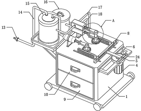
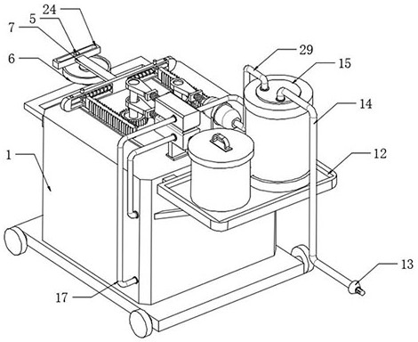
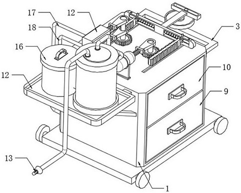
[0035] see Figure 1-4 As shown, the present invention is a sputum suction device suitable for hospital care, including a nursing box 1, a sputum suction assembly, and a cleaning assembly. The sputum suction assembly includes a sputum suction tube 15 arranged on one side of the nursing box 1 and Negative pressure mechanism, one end of the sputum suction tube 15 is connected to the sputum suction end 13 through the sputum suction tube 14, and the other end of the sp...


PUM


Abstract

The invention discloses a sputum aspirator suitable for hospital nursing, and relates to the technical field of medical assistance, the sputum aspirator comprises a nursing box body and further comprises a sputum aspiration assembly, the sputum aspiration assembly comprises a sputum aspiration cylinder and a negative pressure mechanism which are arranged on one side of the nursing box body, one end of the sputum aspiration cylinder is connected with a sputum aspiration end through a sputum aspiration pipe, and the other end of the sputum aspiration cylinder is connected with a sputum aspiration cavity; the other end of the sputum suction cylinder is connected with the negative pressure mechanism through the negative pressure pipe, the negative pressure mechanism is used for generating negative pressure in the sputum suction cylinder through the negative pressure pipe, the negative pressure mechanism generates vacuum negative pressure in the sputum suction cylinder through the negative pressure pipe, and under the action of the vacuum negative pressure in the sputum suction cylinder, the sputum suction cylinder can suck the sputum. The sputum suction end sucks sputum clamped in the mouth of a patient into the sputum suction cylinder through the sputum suction pipe, then rapid sputum suction operation is achieved, the flushing mechanism conveys external cleaning liquid into the sputum suction cylinder and flushes the interior of the sputum suction cylinder, after flushing is completed, the liquid suction mechanism pumps out waste liquid in the sputum suction cylinder, and then automatic cleaning treatment on the sputum suction cylinder is completed.

Description

technical field [0001] The invention relates to the technical field of medical assistance, in particular to a sputum suction device suitable for hospital care. Background technique [0002] The respiratory tract is an important channel for exchanging gas inside and outside the human body. The respiratory tract of the elderly and newborns is prone to difficulty in expectoration, resulting in sputum blocking the respiratory tract. During medical care, it is necessary to use a sputum suction device to remove the sputum in the respiratory tract. However, during the nursing period in the hospital, the patient often cannot cough up the sputum spontaneously, which easily blocks the respiratory tract and poses a threat to the patient. [0003] The lack of a reasonable isolation device inside the sputum injection bottle causes the sputum solution to be sucked into the negative pressure source, which leads to difficulties in later cleaning. The application number is 20181032854.3, and...

Claims


Application Information

Patent Timeline
Patent Type & Authority Applications(China)
IPC IPC(8): A61M1/00
CPCY02A50/30
Inventor 霍炎张小辉段永明
Owner 霍炎
Learn More