Plate rolling machine with anti-springback protection function

A plate rolling machine and anti-rebound technology, applied in the direction of cleaning method using gas flow, dust removal, forming tools, etc., can solve the problems of lack of lubrication structure, lack of anti-rebound structure, lack of auxiliary loading and unloading structure, etc., to achieve The effect of convenient loading and unloading

Active Publication Date: 2022-04-22
江苏浩恩机床有限公司
View PDF8 Cites 2 Cited by
  • Summary
  • Abstract
  • Description
  • Claims
  • Application Information

AI Technical Summary

Problems solved by technology

[0008] The purpose of the present invention is to provide a plate bending machine with anti-rebound protection to solve the problems of lack of anti-rebound structure, lack of lubrication structure, lack of auxiliary loading and unloading structure, and lack of dust removal structure proposed in the above background technology

Method used


Image

  • Plate rolling machine with anti-springback protection function
  • Plate rolling machine with anti-springback protection function
  • Plate rolling machine with anti-springback protection function

Examples


Embodiment 2

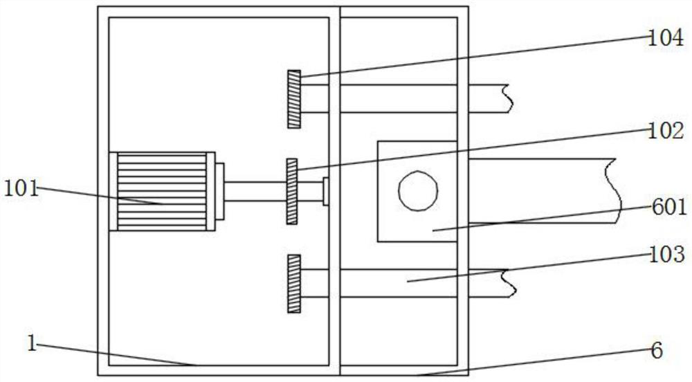
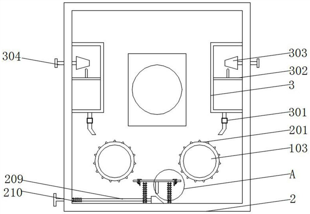
[0045] Example 2: see figure 1 , image 3 and Figure 4 , an embodiment provided by the present invention: a plate bending machine with anti-rebound protection, a ratchet 201 is installed on the inner wall of the holder 2, a spring column 202 is installed on the inner bottom wall of the holder 2, and the spring column 202 Limit plate 203 is installed on the top, and support column 204 is installed on the bottom of limit plate 203, and the two ends of limit plate 203 are all equipped with movable plate 206, and the top of limit plate 203 is equipped with L-shaped limit plate 205, and the limit The bottom of the plate 203 is equipped with a riser 207, the outer wall of the riser 207 is equipped with a first spring 208, and one end of the first spring 208 is connected with the bottom of the movable plate 206, and the outer wall of the fixture 2 is equipped with a moving bar 209, which moves The outer wall of the rod 209 is surrounded by a second spring 210, and a wedge block is...

Embodiment 3

[0046] Example 3: See Figure 5 and Figure 8 , an embodiment provided by the present invention: a plate rolling machine with anti-rebound protection, a lubricating pipe is installed on the bottom of the lubricator 3, a pressure valve 301 is installed on the outer wall of the lubricating pipe, and a pressure valve 301 is installed on the inner wall of the lubricator 3 Extrusion plate 302, extrusion rod is installed on the top of extrusion plate 302, bolt 304 is installed through the outer wall of lubricator 3, extrusion block 303 is installed on one end of bolt 304, lubricating cylinder 401 is installed on the bottom of lubrication box 4, The inner bottom wall of the lubricating cylinder 401 is installed with a striking rod 402, the outer wall of the striking rod 402 is surrounded by a third spring 403, the inner wall of the lubricating cylinder 401 is equipped with a sealing block 404, and the inner top wall of the lubricating cylinder 401 is equipped with a fourth spring. 4...

Embodiment 4

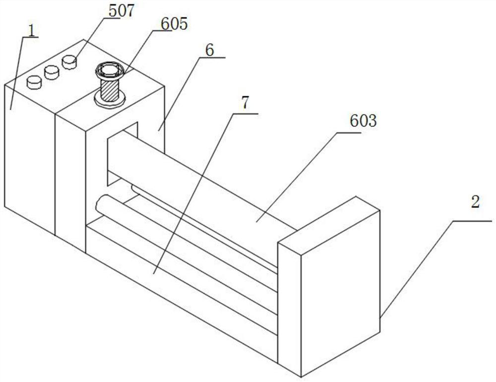
[0047] Example 4: See Figure 7, an embodiment provided by the present invention: a plate bending machine with anti-rebound protection, a gear shaft 501 is installed on the inner wall of the water level gauge 5, a conductive rod 502 is installed on the outer wall of the gear shaft 501, and the top of the water level gauge 5 A gear plate 503 is installed through it, the outer wall of the gear plate 503 is surrounded by a No. 2 spring 504, a floating ball 505 is installed on the top of the gear plate 503, a conductive plate 506 is installed on the inner bottom wall of the water level gauge 5, and the top of the drive box 1 is installed There is a warning light 507, the floating ball 505 inside the water level gauge 5 rises or falls with the liquid level, drives the gear plate 503 to move, the gear plate 503 drives the gear shaft 501 to rotate, when the content of lubricating oil decreases, the conductive rod 502 and the conductive The contact of the plate 506 causes the warning ...


PUM


Abstract

The plate rolling machine comprises a driving box, a fixing device and a bottom plate, the driving box is installed at the top of the bottom plate, the fixing device is installed at the top of the bottom plate, the fixing device and the driving box are located at the two ends of the bottom plate respectively, a lubricator is installed on the inner wall of the fixing device, and the lubricator is installed on the inner wall of the fixing device. A lubricating box is installed on the inner wall of the driving box, a water level device is installed on the inner bottom wall of the lubricating box, and a dust collecting box is installed on the inner wall of the bottom plate. According to the device, springback can be prevented by installing a ratchet wheel and a limiting plate, one end of a transmission roller is inserted into the ratchet wheel, so that the transmission roller rotates to drive the ratchet wheel to rotate, the ratchet wheel rotates to impact a movable plate, the movable plate rotates downwards, a first spring shrinks, and the ratchet wheel can continue to rotate; the transmission roller rotates reversely under the deformation force of the plate, and the movable plate rotates upwards and then is limited by the limiting plate to prevent the movable plate from rotating upwards, so that the plate is prevented from rebounding, and the rebounding prevention function is achieved.

Description

technical field [0001] The invention relates to the technical field of plate rolling machines, in particular to a plate rolling machine with anti-rebound protection. Background technique [0002] The plate rolling machine is a kind of equipment that uses work rolls to bend and form the sheet material. It can form parts of different shapes such as cylindrical parts and conical parts. It is a very important processing equipment. The working principle of the plate rolling machine is through hydraulic pressure. The action of external forces such as mechanical force and mechanical force makes the work roll move, so that the plate is bent or rolled into shape. According to the rotation movement and position changes of the work rolls of different shapes, oval parts, arc parts, cylindrical parts and other parts can be processed. The plate rolling machine can roll metal plates into cylindrical, arc, fan and cone shapes. It is a general-purpose equipment specially used for bending, f...

Claims


Application Information

Patent Timeline
Patent Type & Authority Applications(China)
IPC IPC(8): B21D5/14B21D37/18B21D55/00B08B5/04B08B15/04
CPCB21D5/14B21D37/18B21D55/00B08B5/04B08B15/04Y02P70/10
Inventor 李浩
Owner 江苏浩恩机床有限公司
Why Eureka
Try Eureka