
Movable high-temperature shaft kiln receiving hopper and working method thereof

A receiving hopper and mobile technology, applied in the field of movable high-temperature shaft kiln receiving hopper, can solve the problem that the receiving hopper does not have the ability to handle material safety overflow, cannot meet the production requirements of high-temperature shaft kiln, and the receiving hopper cannot meet the production requirements, etc. problems, to achieve the effect of avoiding the escape of gas in the kiln, improving the sealing of the kiln, and increasing the utilization rate of space

Pending Publication Date: 2022-04-22
ACRE COKING & REFRACTORY ENG CONSULTING CORP DALIAN MCC
View PDF0 Cites 0 Cited by
  • Summary
  • Abstract
  • Description
  • Claims
  • Application Information

AI Technical Summary

Problems solved by technology

[0003] With the continuous optimization and improvement of the high-temperature calcination process, higher and higher requirements are put forward for the feeding system of the kiln. The receiving hopper with a simple structure in the past can no longer meet the existing production requirements.
First of all, the materials contained in the hopper are no longer limited to unburned raw meal balls, and a small amount of under-fired materials that have passed the inspection must also be returned to the kiln for reburning by the hopper to avoid waste of resources. The hopper cannot handle multiple materials in different areas
Secondly, during the production process, the kiln top material level gauge may fail or the feeding and discharging equipment may fail. The traditional receiving hopper does not have the ability to handle material overflow safely, which will lead to production shutdown in serious cases
In addition, the top space of the high-temperature shaft kiln is limited, and the traditional fixed receiving hopper makes the internal maintenance of the kiln body very difficult
At the same time, the material sealing effect of the traditional receiving hopper can no longer meet the production requirements of high-temperature shaft kiln

Method used


Image

  • Movable high-temperature shaft kiln receiving hopper and working method thereof
  • Movable high-temperature shaft kiln receiving hopper and working method thereof
  • Movable high-temperature shaft kiln receiving hopper and working method thereof

Examples


Embodiment Construction

[0037] The specific embodiment of the present invention will be further described below in conjunction with accompanying drawing:

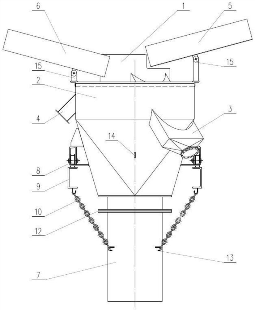
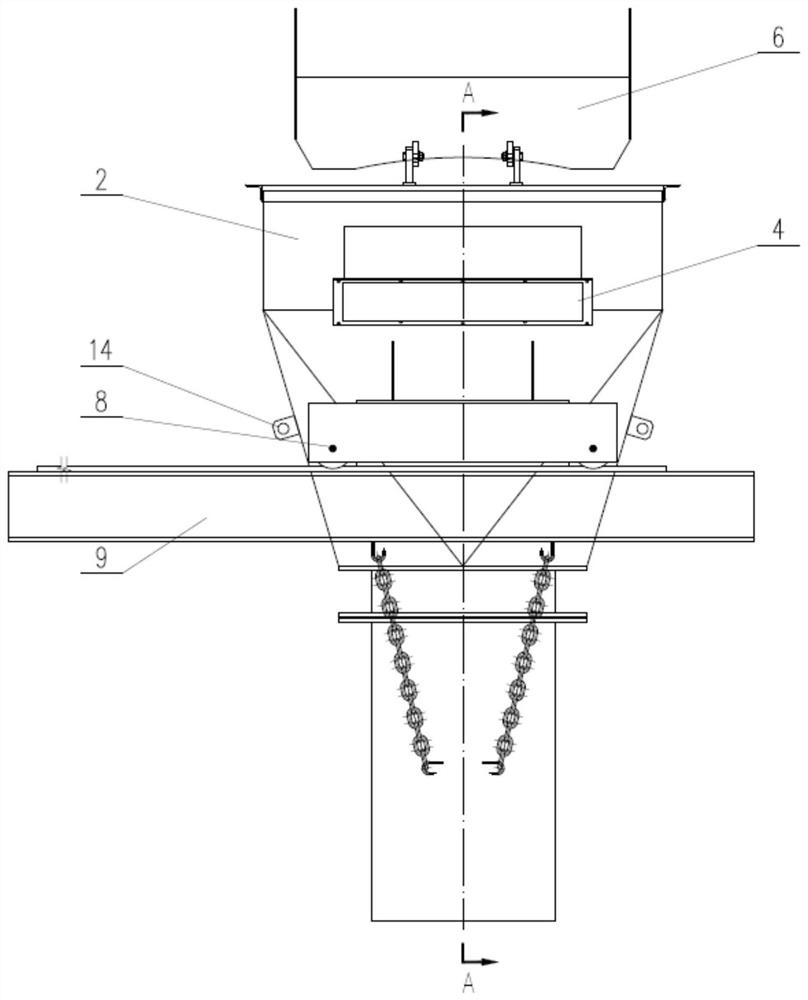
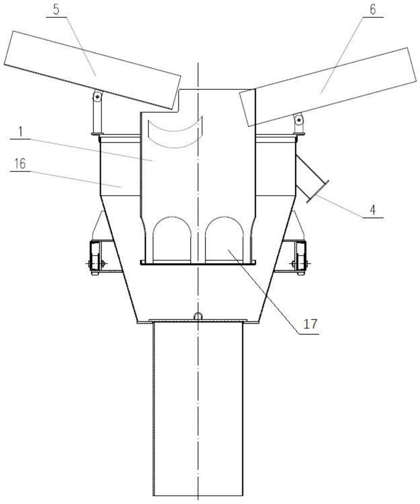
[0038] Such as Figure 1-Figure 4 As shown, a movable high-temperature shaft kiln hopper of the present invention includes a hopper, a feeding pipe 7 and a hopper moving device; the hopper is composed of an inner cylinder 1, an outer cylinder 2, an inner cylinder overflow pipe 3. The outer cylinder overflow pipe 4, the inner cylinder feeding chute 5, and the outer cylinder feeding chute 6. The moving device for the receiving hopper is composed of a roller 8 and a track 9; the inner cylinder 1 and the outer cylinder 2 are vertically arranged, and the two The two are coaxially sleeved together, the bottom surface of the inner cylinder 1 is higher than the bottom surface of the outer cylinder 2; the upper side of the inner cylinder 1 is provided with an inner cylinder feeding chute 5, and the upper part of the inner cylinder 1 on the corresponding si...


PUM


Abstract

The invention relates to a movable high-temperature shaft kiln receiving hopper and a working method thereof. The movable high-temperature shaft kiln receiving hopper comprises a receiving hopper body, a discharging pipe and a receiving hopper moving device. The receiving hopper is composed of an inner cylinder, an outer cylinder, an inner cylinder overflow pipe, an outer cylinder overflow pipe, an inner cylinder feeding chute and an outer cylinder feeding chute. The receiving hopper moving device is composed of rollers and rails. The receiving hopper can adapt to various working conditions, has the safe overflow capacity and can move integrally, the convenience of internal maintenance of a kiln body is greatly improved, and the material sealing effect of the receiving hopper is further improved.

Description

technical field [0001] The invention relates to the technical field of high-temperature shaft kilns, in particular to a movable high-temperature shaft kiln receiving hopper and a working method thereof. Background technique [0002] High-temperature shaft kiln is a kind of thermal kiln equipment, which is used for calcining various high-purity refractory raw materials. The material in the kiln moves continuously from top to bottom. The top of the high-temperature shaft kiln is usually equipped with a fixed receiving hopper, which is used to add raw pellets to the kiln, and at the same time plays a certain role in material sealing to prevent the gas from escaping from the kiln or the air from outside the kiln from being sucked in. [0003] With the continuous optimization and improvement of the high-temperature calcination process, higher and higher requirements are put forward for the feeding system of the kiln, and the receiving hopper with a simple structure in the past c...

Claims


Application Information

Patent Timeline
Patent Type & Authority Applications(China)
IPC IPC(8): B65G65/40B65G11/02F27B1/20F27B1/10F27B1/28
CPCB65G65/40B65G11/026F27B1/20F27B1/10F27B1/28
Inventor 姚苏哲王海波陈昌林
Owner ACRE COKING & REFRACTORY ENG CONSULTING CORP DALIAN MCC
Learn More