Swing type laser welding device capable of finely adjusting focal length

A laser welding and swinging technology, applied in the direction of laser welding equipment, welding equipment, metal processing equipment, etc., can solve the problems of defocus, welding spot size, energy unevenness, etc., achieve parallel exit light, avoid defocus problems, The effect of energy uniformity

Pending Publication Date: 2022-04-29
西安荷佐里机电科技有限公司
View PDF0 Cites 3 Cited by
  • Summary
  • Abstract
  • Description
  • Claims
  • Application Information

AI Technical Summary

Problems solved by technology

[0004] The purpose of the present invention is to provide a swing-type laser welding device that can finely adjust the focal length, so as to solve the problem that the existing swing-type laser welding machine is prone to defocusing, resulting in uneven welding spot size and energy

Method used


Image

  • Swing type laser welding device capable of finely adjusting focal length
  • Swing type laser welding device capable of finely adjusting focal length
  • Swing type laser welding device capable of finely adjusting focal length

Examples


Embodiment Construction

[0023] The present invention will be described in detail below in conjunction with the accompanying drawings and specific embodiments.

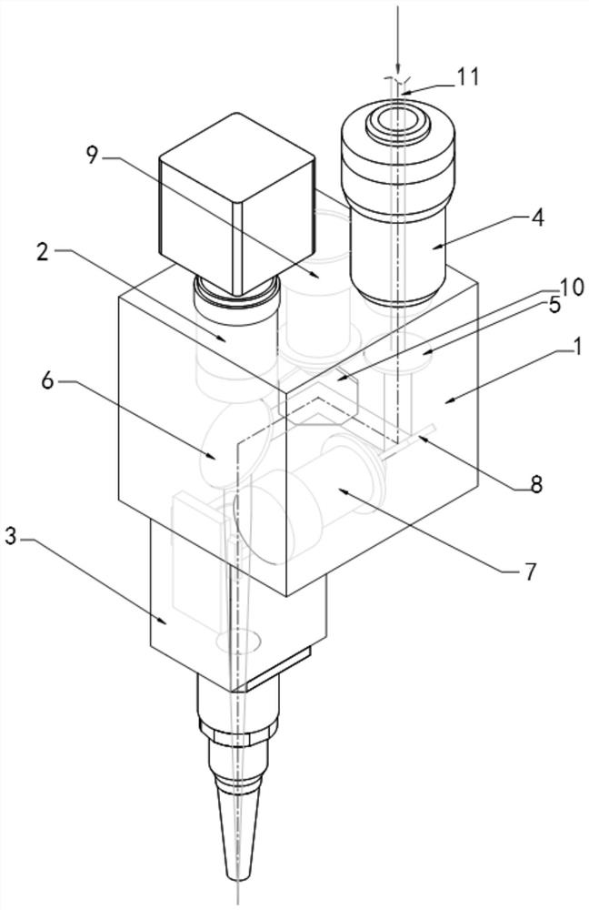
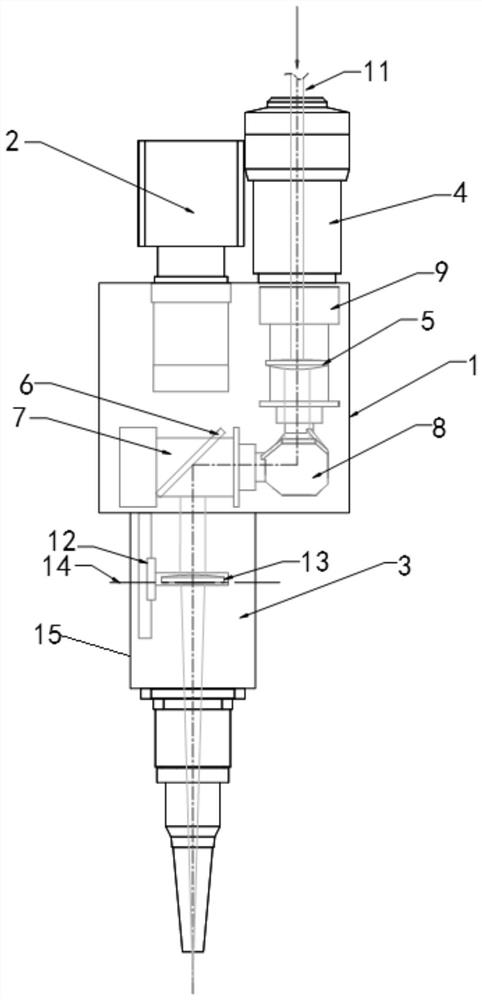
[0024] The invention provides a swing type laser welding device capable of finely adjusting the focal length, the structure is as follows figure 1 As shown, it includes a hollow support 1, a CCD camera 2 and a QBH fiber interface 4 are respectively arranged on the hollow support 1, and a laser focusing assembly 3 is arranged at the bottom of the hollow support 1 and directly below the CCD camera 2, and the hollow support 1 is provided with an X drive motor 7, a Y drive motor 9, a beam expander 5, and a fixed beam splitter 6. The X drive motor 7 and the Y drive motor 9 are respectively arranged on two different surfaces of the hollow support 1 and are different from each other. The surface is vertical, and the optical angle of the rotating shafts of X driving motor 7 and Y driving motor 9 does not exceed 24°. The mirror reflector 10, the beam...


PUM

PropertyMeasurementUnit
angleaaaaaaaaaa

Abstract

The swing type laser welding device comprises a hollow support, a CCD camera and a QBH optical fiber interface are arranged on the hollow support, a laser focusing assembly is arranged at the bottom of the hollow support and located under the CCD camera, and an X driving motor, a Y driving motor, a beam expander and a fixed spectroscope are arranged in the hollow support. An X galvanometer reflecting mirror is arranged on a rotating shaft of the X driving motor, a Y galvanometer reflecting mirror is arranged on a rotating shaft of the Y driving motor, the beam expanding mirror is arranged right above the X galvanometer reflecting mirror, and the fixed spectroscope is arranged right below the CCD camera. The welding device solves the problems that an existing swing type laser welding machine is prone to defocusing, and consequently welding spots are not uniform in size and energy.

Description

technical field [0001] The invention belongs to the technical field of laser welding, and relates to a swing-type laser welding device capable of finely adjusting the focal length. Background technique [0002] With the continuous improvement of industrial production requirements for welding technology, laser welding has been widely used in various welding occasions due to its advantages of high efficiency, high precision, and small heat-affected zone. For objects to be welded with wide weld seams, there are already There are various oscillating laser welding machines. [0003] The optical path structure inside the existing oscillating laser welding machine includes a laser focusing mirror, but generally the laser focusing mirror is simply fixed at the light outlet of the welding machine to achieve the focusing effect. However, in practical applications, some welding objects have height differences due to uneven surfaces or other reasons during the welding process, resultin...

Claims


Application Information

Patent Timeline
Patent Type & Authority Applications(China)
IPC IPC(8): B23K26/046B23K26/06B23K26/064B23K26/21B23K26/70B23K26/08
CPCB23K26/046B23K26/064B23K26/0643B23K26/21B23K26/702B23K26/08
Inventor 魏美乐
Owner 西安荷佐里机电科技有限公司
Why Eureka
Try Eureka