
Pull rope type displacement sensor capable of realizing self-calibration

A displacement sensor and rope-drawn technology, which is applied in the direction of instruments and measuring devices, can solve the problems of reducing the service life of the device, excessively fast retracting speed of the wire rope, and reducing the detection accuracy of the device, so as to increase the service life, increase the scope of use, and realize The effect of automatic calibration

Active Publication Date: 2022-04-29
河南省计量测试科学研究院
View PDF7 Cites 0 Cited by
  • Summary
  • Abstract
  • Description
  • Claims
  • Application Information

AI Technical Summary

Problems solved by technology

[0003] Most of the existing pull-rope displacement sensors are composed of a shell, a steel wire rope, a rotating shaft, a vortex spring and a sensor. The rotating shaft is pulled by the wire rope to rotate, and the rotating shaft drives the induction components in the sensor to rotate when rotating, thereby obtaining the steel wire rope. The length of the pull-out, by setting the vortex spring in the rotating shaft, realizes that when the wire rope is released, the elasticity is used to drive the rotating shaft to rotate in the opposite direction, thereby retracting the wire rope, but after long-term use, the vortex spring will mostly appear elastic Fatigue, resulting in that when the wire rope is released, the elasticity of the vortex spring cannot fully retract the wire rope through the rotating shaft, reducing the service life of the device
[0004] When the existing pull-rope displacement sensor is in use, the rotating shaft is driven to rotate by pulling the wire rope, and the winding mode of the wire rope on the rotating shaft is in close contact with each other in an alternate manner. When the wire rope is retracted, the wire rope may be retracted too fast. As a result, the steel wire ropes are stacked, and when the stacked steel wire ropes are pulled out, the length value of the pulled out steel wire ropes deviates from the length value obtained by rotating the rotating shaft one revolution, thereby reducing the detection accuracy of the device
[0005] When the existing pull-rope displacement sensor is in use, the rotating shaft can be driven to rotate by directly pulling the wire rope. However, if the moving direction of the object is inconsistent with the direction of the rope, the object will drive the end of the wire rope to deflect when it moves. However, even when the end of the steel wire rope is deflected, it will pull the rotating shaft to rotate at a certain angle, that is, the object does not move during the process that the end of the steel wire rope protrudes during deflection, resulting in a discrepancy between the measurement results of the device and the actual results. error, so that the device cannot cope with the situation that the direction of object movement is inconsistent with the direction of the rope, reducing the range of use of the device

Method used


Image

  • Pull rope type displacement sensor capable of realizing self-calibration
  • Pull rope type displacement sensor capable of realizing self-calibration
  • Pull rope type displacement sensor capable of realizing self-calibration

Examples


Embodiment Construction

[0048] The following will clearly and completely describe the technical solutions in the embodiments of the present invention with reference to the accompanying drawings in the embodiments of the present invention. Obviously, the described embodiments are only some, not all, embodiments of the present invention. Based on the embodiments of the present invention, all other embodiments obtained by persons of ordinary skill in the art without making creative efforts belong to the protection scope of the present invention.

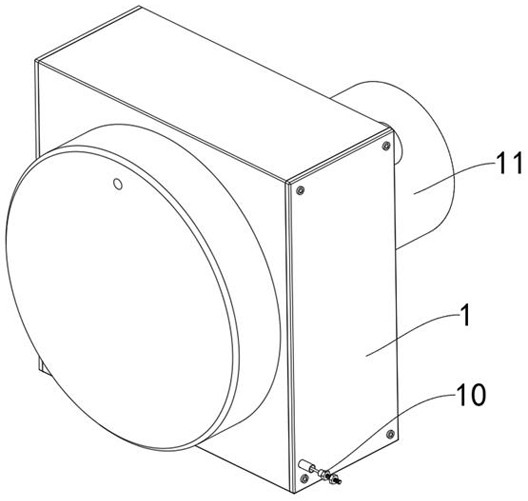
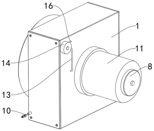
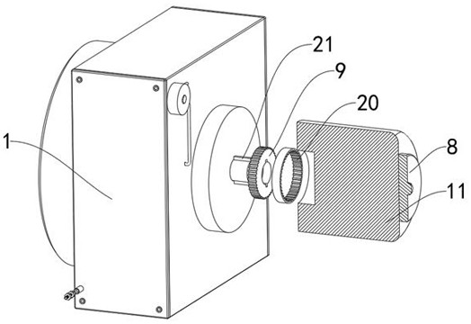
[0049] Such as Figure 1 to Figure 9 As shown, in the embodiment of the present invention, a drawstring type displacement sensor capable of self-calibration includes a housing 1, the inner cavity of the housing 1 is movably connected with a rotating shaft 2, and the left end of the inner cavity of the rotating shaft 2 is fixedly installed with a Ball screw 1 3, the surface of ball screw 1 3 is meshed with moving magnetic plate 4, the right side of the inner ca...


PUM


Abstract

The invention belongs to the technical field of pull rope type displacement sensors, and discloses a pull rope type displacement sensor capable of realizing self-calibration, which comprises a shell, a rotating shaft is movably connected to an inner cavity of the shell, a first ball screw is fixedly mounted at the left end of an inner cavity of the rotating shaft, and a movable magnetic plate is meshed with the surface of the first ball screw. A first positioning rod is fixedly installed on the right side face of an inner cavity of the shell, and a first fixed magnetic block is fixedly installed on the left side face of an inner cavity of the rotating shaft. The first fixed magnetic block and the second fixed magnetic block are arranged on the left side and the right side of the movable magnetic plate correspondingly, the first fixed magnetic block and the second fixed magnetic block apply the leftward movement tendency to the movable magnetic plate all the time through magnetic force, when the steel wire rope is loosened, the steel wire rope is driven to retract automatically, in the process of pulling out and retracting the steel wire rope, elasticity does not exist, and the safety of the steel wire rope is improved. Therefore, the situation that the steel wire rope cannot be smoothly retracted due to elastic fatigue is avoided, and the service life of the device is prolonged.

Description

technical field [0001] The invention belongs to the technical field of a drawstring displacement sensor, in particular to a drawstring displacement sensor capable of self-calibration. Background technique [0002] The drawstring displacement sensor is a real-time monitoring device for mechanical linear motion with small size, simple installation, stable performance and high cost performance. It is widely used in various industries to detect the displacement of moving objects. [0003] Most of the existing pull-rope displacement sensors are composed of a shell, a steel wire rope, a rotating shaft, a vortex spring and a sensor. The rotating shaft is pulled by the wire rope to rotate, and the rotating shaft drives the inductive components in the sensor to rotate when rotating, thereby obtaining the steel wire rope. The length of the pull-out, by setting the vortex spring in the rotating shaft, realizes that when the wire rope is released, the elasticity is used to drive the rot...

Claims


Application Information

Patent Timeline
Patent Type & Authority Applications(China)
IPC IPC(8): G01B21/02
CPCG01B21/02G01B21/042Y02E10/72
Inventor 朱记全贾晓杰王晓伟苏清磊范乃胤朱荣全刘路
Owner 河南省计量测试科学研究院
Learn More