LED backlight driving circuit and driving method based on low potential end switch control
A backlight drive circuit and backlight drive technology, applied in the use of semiconductor lamps, static indicators, instruments, etc., can solve the problems of inability to improve the brightness of a single LED light string alone, poor display effect, and increased control difficulty. Eliminate the phenomenon of afterimage, save the cost of circuit structure, and avoid the effect of high current
- Summary
- Abstract
- Description
- Claims
- Application Information
AI Technical Summary
Problems solved by technology
Method used
Image

Examples
Embodiment 1
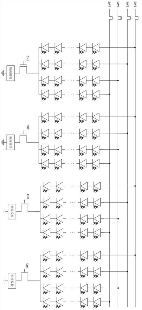
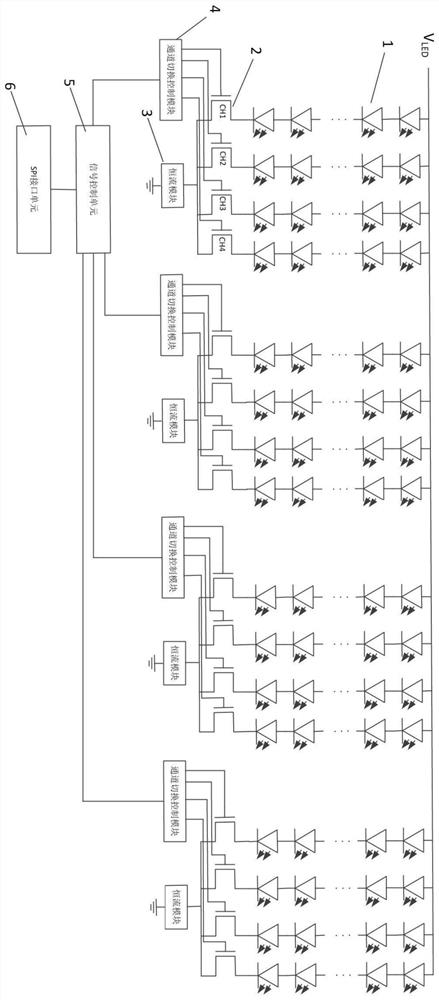
[0060] In this embodiment, every four LED light strings form a group, and the four LED light strings share one constant current module. Since there are four LED light strings sharing the constant current module, in the case that the LED light strings of all channels equally share the constant current module, the upper limit of the duty ratio that can be shared by the LED light strings of each channel is 25%. And the sum of the on-duty ratios of the LEDs of all channels is at most 100%, that is, the sum of all the duty ratios of the constant current modules shared by the four channels is at most 100%.
[0061] However, when the brightness requirement duty cycle of a certain LED light string exceeds 25%, in the LED backlight driving method of this embodiment, the other LED light strings in the same group fail to reach the duty cycle margin of 25% duty cycle. Supplemented to LED light strings that require increased brightness, so that the LED light string breaks through the 25% d...
Embodiment 2
[0066] Same as Embodiment 1, in this embodiment, every four LED light strings form a group, and the four LED light strings share one constant current module. Since four LED light strings share the constant current module, the maximum duty cycle of the LED light strings of each channel is 25% under the condition that the LED light strings of all channels equally share the constant current module. However, when the brightness requirement of a certain LED light string exceeds 25%, in the LED backlight driving method of this embodiment, the duty cycle margin of other LED light strings in the same group that fails to reach the 25% duty cycle is supplemented to the required In the LED light string with increased brightness, the LED light string breaks through the duty ratio limit of 25%.
[0067] For example, the brightness requirements of the LED light strings of channel 1, channel 2, channel 3, and channel 4 are 60%, 15%, 20%, and 25%, respectively. From the above brightness requ...
Embodiment 3
[0074] Same as Embodiment 1, in this embodiment, every four LED light strings form a group, and the four LED light strings share one constant current module. Since there are four LED light strings sharing the constant current module, the maximum duty cycle of the LED light strings of each channel is 25% under the condition that the LED light strings of all channels equally share the constant current module. However, when the brightness requirement of a certain LED light string exceeds 25%, in the LED backlight driving method of this embodiment, the duty cycle margin of other LED light strings in the same group that fails to reach the 25% duty cycle is supplemented to the required In the LED light string with increased brightness, the LED light string breaks through the duty ratio limit of 25%.
[0075] For example, the brightness requirements of the LED light strings of channel 1, channel 2, channel 3, and channel 4 are 60%, 15%, 20%, and 25%, respectively. From the above bri...
PUM
 Abstract
Description
Claims
Application Information
 - R&D
- Intellectual Property
- Life Sciences
- Materials
- Tech Scout
- Unparalleled Data Quality
- Higher Quality Content
- 60% Fewer Hallucinations
Browse by: Latest US Patents, China's latest patents, Technical Efficacy Thesaurus, Application Domain, Technology Topic, Popular Technical Reports.
© 2025 PatSnap. All rights reserved.Legal|Privacy policy|Modern Slavery Act Transparency Statement|Sitemap|About US| Contact US: help@patsnap.com