Supercharge Your Innovation With Domain-Expert AI Agents!

Magnetic circuit switch type cantilever beam structure piezoelectric-electromagnetic composite vibration power generation device

An electromagnetic composite and vibration power generation technology, which is applied to piezoelectric effect/electrostrictive or magnetostrictive motors, electromechanical devices, generators/motors, etc. The effect of improving power generation efficiency and enhancing vibration damping effect

Pending Publication Date: 2022-04-29
ZHONGBEI UNIV
View PDF0 Cites 0 Cited by
  • Summary
  • Abstract
  • Description
  • Claims
  • Application Information

AI Technical Summary

Problems solved by technology

The disadvantage of this method is that the efficiency of electromagnetic power generation is low, and mainly relying on piezoelectric power generation cannot obtain more energy for power supply

Method used


Image

  • Magnetic circuit switch type cantilever beam structure piezoelectric-electromagnetic composite vibration power generation device
  • Magnetic circuit switch type cantilever beam structure piezoelectric-electromagnetic composite vibration power generation device
  • Magnetic circuit switch type cantilever beam structure piezoelectric-electromagnetic composite vibration power generation device

Examples


Embodiment 1

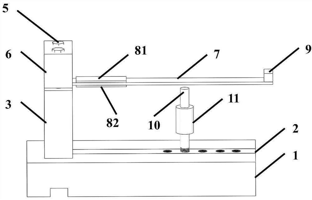
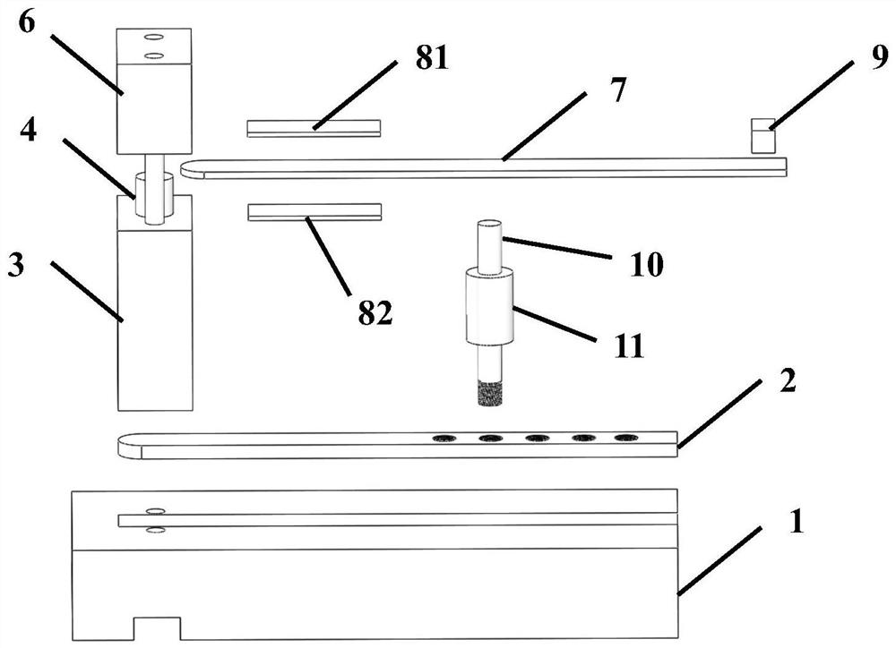
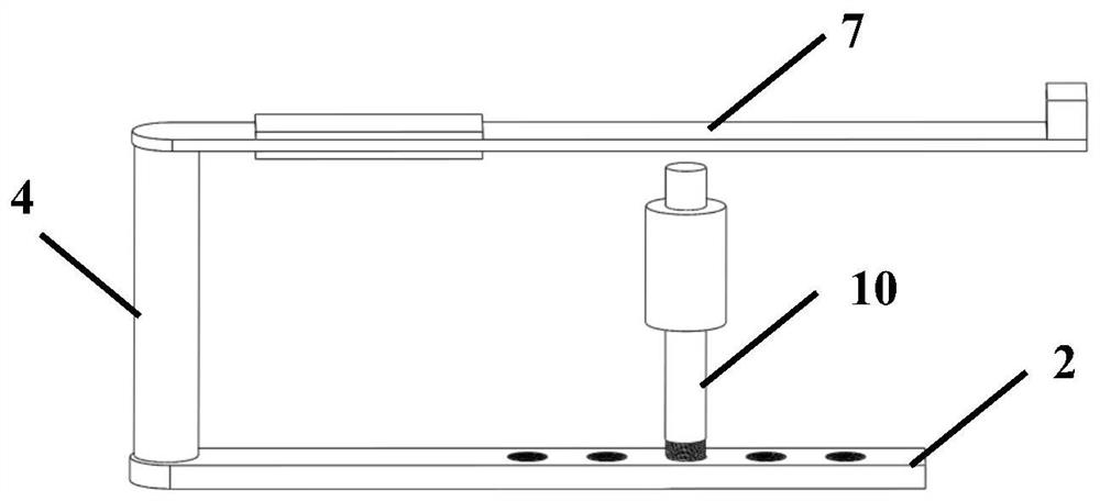
[0024] The invention provides a piezoelectric-electromagnetic composite vibration power generation device with a magnetic circuit switch type cantilever beam structure, such as figure 1 and figure 2 As shown, it includes a base 1 , a bottom plate 2 , a bracket 3 , a permanent magnet 4 , a fixing frame 6 , a cantilever beam 7 , a piezoelectric sheet, a weight 9 , a coil column 10 , and a coil 11 . The base 1 is made of non-ferromagnetic material, and the material of the base 1 is plexiglass. The base 1 is provided with a groove, and the bottom plate 2 is fixed in the groove. The bottom plate 1 is made of soft magnetic material, so as to facilitate the conduction of magnetic field lines. The bracket 3 is fixed on the base 1 . The width of the bottom plate 2 is greater than 1 cm and less than 1.5 cm. The material of the bracket 3 is non-ferromagnetic material, and the material of the bracket 3 is organic glass. The permanent magnet 4 runs through the support 3, and the heig...

Embodiment 2

[0029]On the basis of Embodiment 1, a screw hole is provided on the upper edge of the bottom plate 2, and the coil column 10 is arranged in the screw hole. There are five screw ports, and the five screw ports are distributed along the length direction of the base plate 2 . The bottom end of the coil column 10 is provided with threads, and is fixed in the screw opening. In application, the coil post 10 can be arranged in different screw ports, so as to select the optimal working frequency band and power generation efficiency.

Embodiment 3

[0031] On the basis of Embodiment 2, the base 1, the bracket 3, and the fixed frame 6 are provided with two through holes, and the base 1, the bracket 3, and the fixed frame 6 are fixed together by two bolts and two fastening screws, This enables the permanent magnet 4, the cantilever beam 7 and the bottom plate 2 to be in stable contact.


PUM


Abstract

The invention relates to the field of energy collection, in particular to a magnetic circuit switch type cantilever beam structure piezoelectric-electromagnetic composite vibration power generation device which comprises a base, a bottom plate, a support, a permanent magnet, a fixing frame, a cantilever beam, a piezoelectric plate, a weight, a coil column and a coil. A groove is formed in the base, the bottom plate is fixed in the groove, the support is fixed to the base, the permanent magnet penetrates through the support, the fixed end of the cantilever beam is fixed to the top of the support through the fixing frame, the permanent magnet is connected with the bottom plate and the cantilever beam, the piezoelectric plate is arranged near the fixed end of the cantilever beam, and the weight is fixed near the free end of the cantilever beam. The coil column is vertically fixed on the bottom plate, the coil surrounds the coil column, and the cantilever beam, the bottom plate and the coil column are all made of soft magnetic materials. A main body of the device is made of soft magnetic materials, connection and disconnection of a magnetic loop are achieved through vertical oscillation of the cantilever beam, piezoelectric plate power generation and electromagnetic induction power generation are fully combined, the power generation efficiency of the device is improved, and the device has good application prospects in the field of vibration energy collection.

Description

technical field [0001] The invention relates to the field of energy collection, in particular to a piezoelectric-electromagnetic composite vibration power generation device with a magnetic circuit switch type cantilever beam structure. Background technique [0002] With the rapid development of the Internet of Things era, wireless sensor networks and low-power electronic devices have been widely used. Traditionally, there are two main ways to provide power for these devices, namely batteries and external power cords. The use of batteries will greatly increase the maintenance cost of these devices, especially for multi-node wireless sensor networks; external power lines are prone to problems such as line failures, which will limit the movement of sensor nodes and greatly reduce the application effect . Therefore, ambient energy harvesting plays a pivotal role in the Internet of Things era, which can provide continuous and stable energy output for nodes in different environm...

Claims


Application Information

Patent Timeline
Patent Type & Authority Applications(China)
IPC IPC(8): H02N2/18H02K35/02
CPCH02N2/186H02K35/02
Inventor 崔娟郑永秋薛晨阳高翔郝聪聪李刚
Owner ZHONGBEI UNIV
Features
  • R&D
  • Intellectual Property
  • Life Sciences
  • Materials
  • Tech Scout
  • Unparalleled Data Quality
  • Higher Quality Content
  • 60% Fewer Hallucinations
Learn More