Delay sending method and device of data, electronic equipment and storage medium

A transmission method and data technology, applied in the field of communication, can solve the problems of large buffer demand, asynchronous transmission delay and air interface signals, etc., and achieve the effect of ensuring transmission delay, eliminating transmission delay differences, and reducing the demand for hardware resources.

Pending Publication Date: 2022-04-29
CHINA TELECOM CORP LTD
View PDF0 Cites 1 Cited by
  • Summary
  • Abstract
  • Description
  • Claims
  • Application Information

AI Technical Summary

Problems solved by technology

Each remote radio unit is remoted to different locations in the room. Due to the different locations, the length of the optical fiber connecting each remote radio unit to the extension unit is different. The resulting difference in transmission delay will cause the remote radio unit to The transmitted air interface signal is not synchronized
[0003] The existing synchronization method / delay compensation method mainly uses RRU (Remote Radio Unit, remote radio module) to cache uplink and downlink data. The longer the distance is, the greater the buffering requirement is. In the extended small base station, the method of cell merging is used. In some cases, multiple RRUs belong to the same cell, that is, the same data is cached in multiple RRUs. The more RRUs, the more hardware resources RRUs use for caching, and the greater the waste.

Method used


Image

  • Delay sending method and device of data, electronic equipment and storage medium
  • Delay sending method and device of data, electronic equipment and storage medium
  • Delay sending method and device of data, electronic equipment and storage medium

Examples


Embodiment Construction

[0066] Exemplary embodiments of the present application will be described in more detail below with reference to the accompanying drawings. Although exemplary embodiments of the present application are shown in the drawings, it should be understood that the present application may be embodied in various forms and should not be limited to the embodiments set forth herein. Rather, these embodiments are provided so that the present application can be more thoroughly understood, and the scope of the present application can be fully conveyed to those skilled in the art.

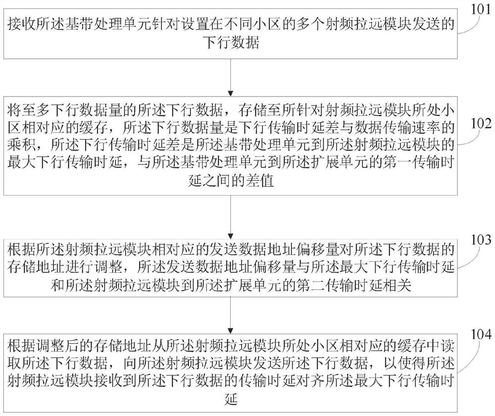
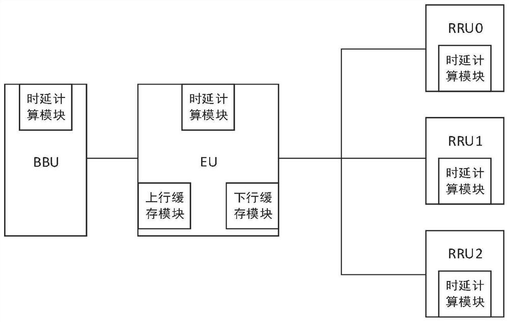
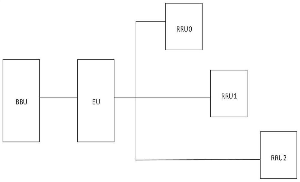
[0067] figure 1 It is a flow chart of the steps of a method for delayed sending of data provided in the embodiment of this application, which is applied to such as figure 2 The EU (Expander Unit, expansion unit) in the described data transmission system, the system also includes at least: a BBU (Base band Unite, baseband processing unit) that is communicatively connected with the expansion unit, and distributed ...


PUM


Abstract

The invention provides a data delay sending method and device, electronic equipment and a storage medium, which are applied to the technical field of communication, and the method comprises the following steps: receiving downlink data sent by a baseband processing unit for a plurality of radio remote modules arranged in different cells; and storing the downlink data with at most downlink data volume to a cache corresponding to a cell in which the radio remote module is located, and adjusting the storage address of the downlink data according to the data sending address offset corresponding to the radio remote module, and according to the adjusted storage address, reading the downlink data from a cache corresponding to a cell in which the remote radio frequency module is located, and sending the downlink data to the remote radio frequency module. According to the invention, the transmission delay difference caused by the remote distance difference between different remote radio frequency modules and the extension unit can be eliminated, and the demand for the hardware resources of the remote radio frequency modules is reduced.

Description

technical field [0001] The present application belongs to the technical field of communication, and in particular, relates to a data delay sending method, device, electronic equipment and storage medium. Background technique [0002] In indoor coverage scenarios, extended small base stations are usually used for wireless signal coverage. The extended small base station adds an extension unit, allowing one baseband unit to be extended and connected to multiple remote radio units. Each remote radio unit is remoted to different locations in the room. Due to the different locations, the length of the optical fiber connecting each remote radio unit to the extension unit is different. The resulting difference in transmission delay will cause the remote radio unit to The transmitted air interface signals are not synchronized. [0003] The existing synchronization method / delay compensation method mainly uses RRU (Remote Radio Unit, remote radio module) to cache uplink and downlink...

Claims


Application Information

Patent Timeline
Patent Type & Authority Applications(China)
IPC IPC(8): H04W4/33H04W28/02H04W28/14H04W88/08
CPCH04W4/33H04W28/0205H04W28/14H04W88/085
Inventor 黄云飞闵锐梁力维梁柏青伍彦文李颖魏广宁廖粤飞
Owner CHINA TELECOM CORP LTD
Why Eureka
Try Eureka