Ethernet transmission device
A transmission device and Ethernet technology, which is applied in the field of Ethernet communication, can solve the problems of no intermediate level, high cost, and connection, etc., and achieve the effect of increasing the transmission distance and increasing the transmission rate
Inactive Publication Date: 2010-11-10
NEW H3C TECH CO LTD
View PDF1 Cites 0 Cited by
- Summary
- Abstract
- Description
- Claims
- Application Information
AI Technical Summary
Problems solved by technology
In addition, the existing Ethernet transmission is still limited to the 4-pair wire method stipulated in the standard, and it is impossible to share the rate to more wire pairs. This is because the thinking direction of the existing technology is limited under the framework of the standard. On the other hand, it has not found a suitable solution to the cost of large logarithmic cables. Finally, the existing Ethernet rate levels are limited to three levels of 10 / 100 / 1000M, and there is no intermediate level rate, such as 30M. 500M
However, in actual networking applications, there are often situations where 100M is insufficient and 1000M is too much (and 1000M often requires optical transmission, which is costly and requires a license for laying optical fibers), which makes it impossible to achieve a reasonable allocation of resources, and users cannot get the closest products in demand
Method used
View moreImage
Smart ImageViewing Examples
Examples
Embodiment Construction
Login to View More PUM
 Abstract
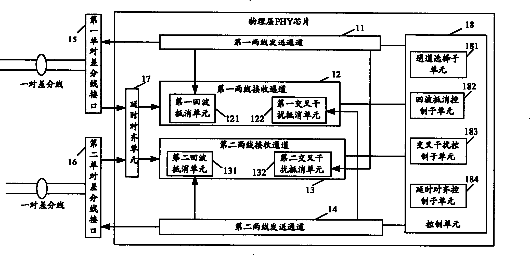
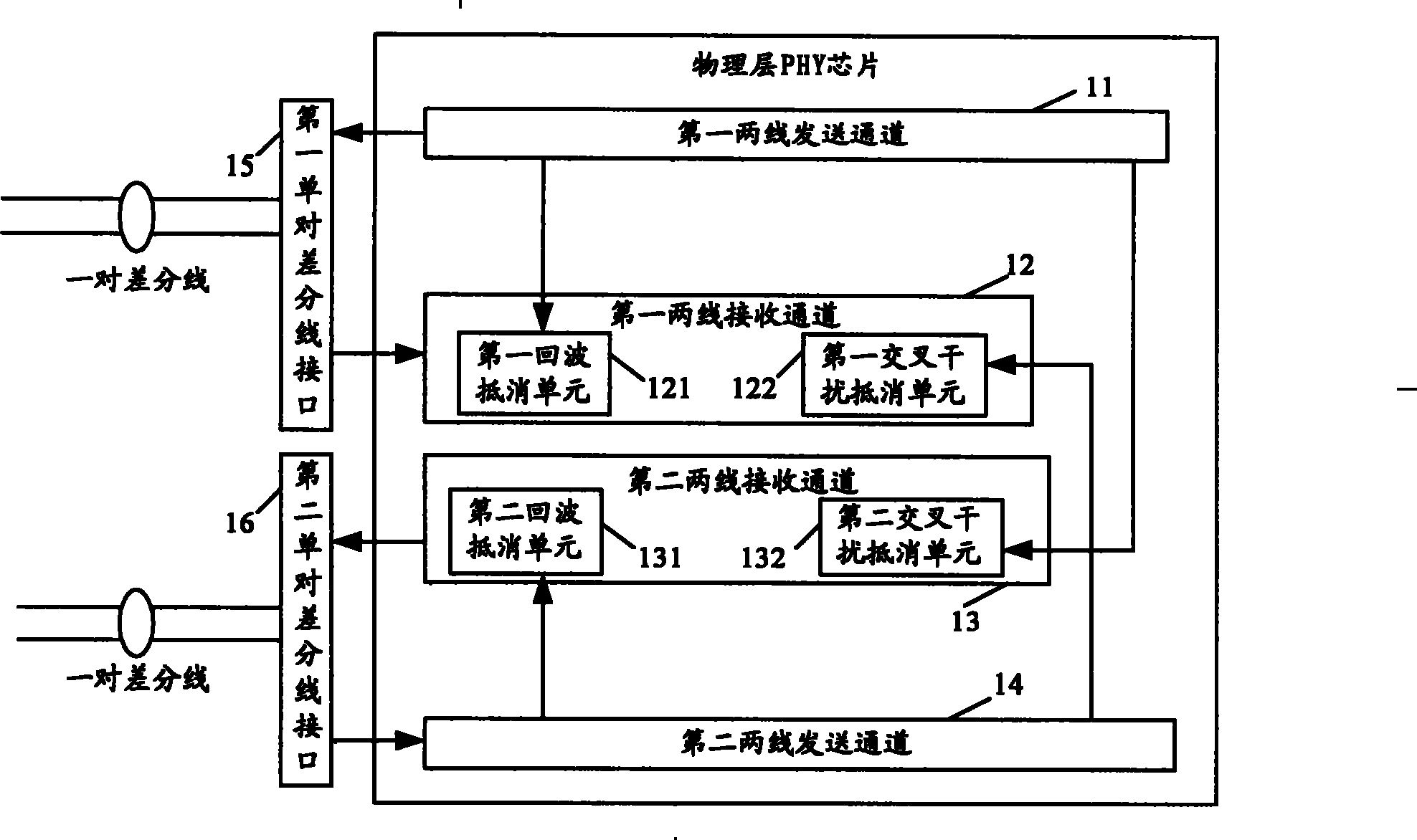
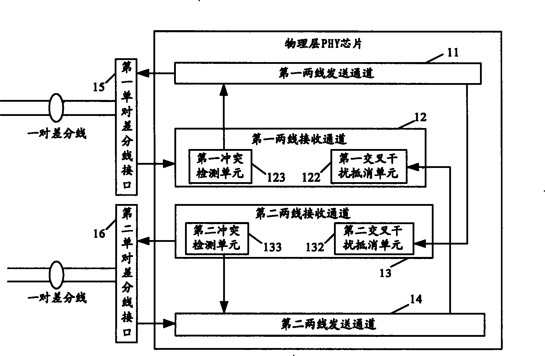
The invention discloses an Ethernet transmission device, including at least two single-pair differential interfaces serving the same physical port and at least two two-line receiving-transmitting channels corresponding with the single-pair differential interfaces. The transmission speed of each of the two channels should be equal to or lower than 100 mega. The channels should include an alternative disturbance offsetting unit to eliminate the impact on the receiving signals of the channels from other channels through local signals of the corresponding single-pair differential interface. The invention can support the parallel bundled transmission of multiple differential lines under the two-line mode, and is compatible with the current standard four-line transmission mode.
Description
An ethernet transmission device technical field The invention relates to the field of Ethernet communication, in particular to an Ethernet transmission device. Background technique The existing standard 10 / 100M Ethernet transmission adopts four-wire (two-pair) transmission technology. One differential line pair is dedicated to sending Ethernet data from the local to the opposite end, and the other differential line pair is dedicated to receiving data from the opposite end. Signal. Furthermore, in the existing 10 / 100M Ethernet transmission technology, each Ethernet physical port needs at least two pairs of differential lines for data transmission and reception, so more cable resources are occupied. For this reason, the applicant proposed a two-wire network with a transmission rate lower than Gigabit in the patent application document with the application number 200610099454.4 and the name "An Ethernet transmission device and method suitable for lower than Gigabit transmis...
Claims
Login to View More Application Information
Patent Timeline
 Patent Type & Authority Patents(China)
IPC IPC(8): H04B3/34
Inventor 于洋
Owner NEW H3C TECH CO LTD
Features
- R&D
- Intellectual Property
- Life Sciences
- Materials
- Tech Scout
- Unparalleled Data Quality
- Higher Quality Content
- 60% Fewer Hallucinations
Learn More Browse by: Latest US Patents, China's latest patents, Technical Efficacy Thesaurus, Application Domain, Technology Topic, Popular Technical Reports.
© 2025 PatSnap. All rights reserved.Legal|Privacy policy|Modern Slavery Act Transparency Statement|Sitemap|About US| Contact US: help@patsnap.com


