Drainage device, drainage method and drainage device manufacturing method

A technology of drainage tube and locking device, which is applied in the direction of suction instruments, balloon catheters, catheters, etc., and can solve the problems of increased possibility of inflammation, blockage of the side hole of the pipeline, and influence on the healing process, etc.

Pending Publication Date: 2022-05-03
于从军
View PDF6 Cites 0 Cited by
  • Summary
  • Abstract
  • Description
  • Claims
  • Application Information

AI Technical Summary

Problems solved by technology

Another situation is that the general condition of the body is poor and cannot tolerate complex and long-term anesthesia and surgical operations. The doctor can only simply deal with the effusion site, and some simple drainage tube placement is performed under local anesthesia.
Conventionally placed drainage tubes have the problem that the side hole of the tube is blocked and the drainage effect is reduced. At the same time, the contact stimulation of the general tube to the skin outlet will affect the use experience
[0012] Chronic sinus tracts caused by microbial infection, physical and chemical factor damage, tumors, ischemia, etc. are irregular. In some special cases, even surgery can only remove most of the sinus tracts, and the rest is complicated. Traditional drainage There is a problem that the tube cannot fit well with the sinus, and there is a damage mechanism of excessive tension in the local sinus (as mentioned above), and the sinus itself is in a state of chronic inflammation, and the new larger-scale inflammation Increased likelihood of being induced to affect the healing process
[0013] In short, maintaining the stability and patency of the drainage is often required for treatment. The larger the diameter of the traditional drainage tube, the stronger the drainage capacity and the less likely it is to be blocked. Narrow, twisted and irregular drainage channels are more damaged
The drainage capacity of the traditional drainage tube and the damage to the drainage channel itself are a pair of contradictions that are difficult to reconcile

Method used


Image

  • Drainage device, drainage method and drainage device manufacturing method
  • Drainage device, drainage method and drainage device manufacturing method
  • Drainage device, drainage method and drainage device manufacturing method

Examples


Embodiment Construction

[0231] The protection content of the present invention is not limited to the following examples. Without departing from the spirit and scope of the inventive concept, changes and advantages conceivable by those skilled in the art are all included in the present invention, and the appended claims are the protection scope.

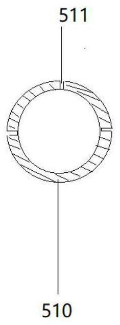
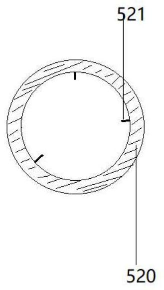
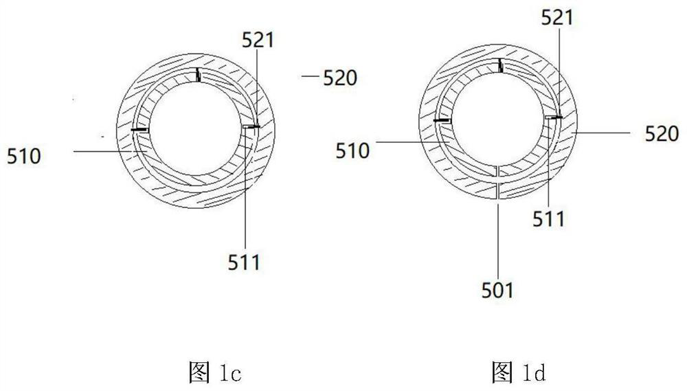
[0232] Figures 1a-1d In the middle, 501-0° notch; 510-inner sleeve; 511-blade matching groove; 520-outer sleeve; 521-metal blade. From left to right: the cross-section of the head end of the inner sleeve 510; the cross-section of the head end of the outer sleeve 520; the cross-section of the head end of the inner and outer sleeves in the fitting state; the head of the inner and outer sleeves in the fitting state with a 0° gap End cross section.

[0233] figure 2 Among them, 400-pipe part; 401-metal tip; 402-filler traffic hole; 403-filler outlet; 404-conical part.

[0234] image 3 In the middle, 901-single capsule tube; 902-double-pass single-capsule ...


PUM


Abstract

The invention discloses a novel drainage device which comprises a drainage tube, a clamping balloon connected with the drainage tube, a clamping balloon filler, a communicating tube, a locking device and a support tube movably arranged in the drainage device. And at least one section of drainage tube wall is a flexible tube wall. When the drainage device is in a non-drainage state, the flexible drainage tube body of the drainage channel is good in shape follow-up performance, small in extrusion and expansion degree on tissues around the drainage tube and light in local inflammatory response; when drainage is needed, the support tube moves to the narrow portion of the drainage channel along the inner side of the drainage tube wall, and the drainage process is completed. The invention further discloses a manufacturing method for manufacturing the clamping balloon, the drainage tube, the communicating tube and related structures of the clamping balloon, the drainage tube and the communicating tube, and the manufacturing method comprises the steps that basic pipelines are manufactured firstly, then the basic pipelines are machined and combined, and related accessories are configured. The drainage device also has a reverse conveying function, and particularly plays an important role in food conveying of the upper digestive tract.

Description

technical field [0001] The invention belongs to the technical field of medical devices, and in particular relates to a drainage device, a drainage method, and a manufacturing method of the drainage device. Background technique [0002] The purpose of medical drainage is to remove the gas and liquid (including blood, pus, inflammatory exudate, bile, gastric juice, intestinal juice, urine, secretion, etc.) accumulated in the body cavity, joint, organ or tissue from the original source. In order to prevent accumulation in the body cavity or surgical field, secondary symptoms of compression, infection or tissue damage. By observing the drainage situation, it is also possible to detect changes in the disease early; after drainage of blood, exudate, tissue secretion, and gas, it can reduce local pressure, reduce the damage of liquid or gas to surrounding tissues, and reduce the possibility of co-infection , It is beneficial to maintain normal physiological activities and promote ...

Claims


Application Information

Patent Timeline
Patent Type & Authority Applications(China)
IPC IPC(8): A61M1/00A61M25/10
CPCA61M25/10A61M25/1011A61M25/1018A61M25/1025A61M25/1027A61M25/0009A61M25/0023A61M25/0043A61M25/005A61M25/0052A61M25/0054A61M25/0068A61M25/007A61M25/008
Inventor 蒋小平于奕飞
Owner 于从军
Why Eureka
Try Eureka