
Plastic bottle laser marking system and method based on machine vision

A laser marking method and machine vision technology, applied in the field of visual laser marking, can solve the problems of one-time marking of difficult workpieces, unfavorable simultaneous positioning of multiple workpieces, and low safety, so as to improve marking accuracy and reliability. Reproducibility and the effect of improving marking efficiency

Inactive Publication Date: 2022-05-03
广东猛犸象智能机器人制造有限公司
View PDF0 Cites 0 Cited by
  • Summary
  • Abstract
  • Description
  • Claims
  • Application Information

AI Technical Summary

Problems solved by technology

[0002] Traditional product coding is mainly inkjet, but it often needs to be in contact with the product and is easy to erase, and the consumables are large, costly, and unfriendly to the environment, while laser coding technology has non-contact non-destructive marking and is environmentally friendly. The advantages of friendliness, high processing accuracy, long-lasting marking, long service life and fast processing efficiency gradually occupy the field of coding
[0003] However, when laser marking machines are used in industrial production at this stage, most operators still need to manually position the items to be marked and manually adjust the focus with experience. The location can only be removed after the coding is completed. This traditional laser marking method not only inevitably affects the marking accuracy, but also difficult to meet the needs of a large number of workpieces for one-time marking. The efficiency is low, and the labor cost is high, and the loading and unloading labor is large. , low security
[0004] In addition, even for laser marking systems that have applied automation technology, the method of using fixed fixtures to position workpieces is not only costly, but also not conducive to the simultaneous positioning of multiple workpieces, and will also cause instability of human positioning errors

Method used


Image

  • Plastic bottle laser marking system and method based on machine vision
  • Plastic bottle laser marking system and method based on machine vision
  • Plastic bottle laser marking system and method based on machine vision

Examples


Embodiment 1

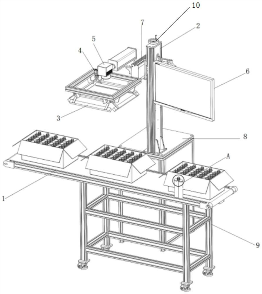
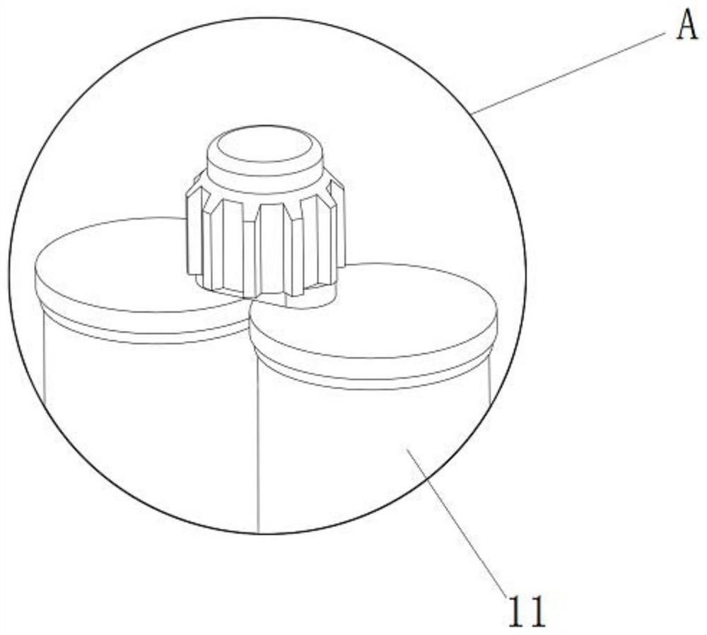
[0042] Such as Figure 1~6 As shown, the embodiment of the present invention provides a laser marking system for plastic bottles based on machine vision, including a transmission mechanism and a marking machine mechanism, the transmission mechanism includes a fixed frame 9 and a conveyor belt 1 installed on the fixed frame 9, marking The mechanism 5 is set up on the side of the conveyor belt 1, and the marking mechanism 5 is used to mark the plastic bottles on the conveyor belt 1.

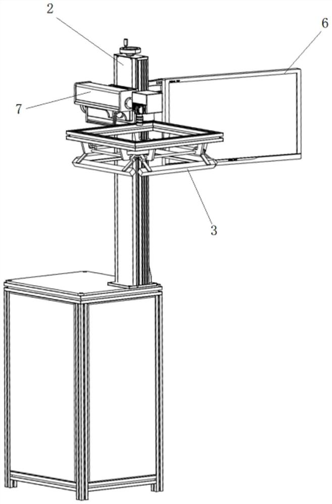
[0043] In this specific embodiment, the marking machine 5 mechanism includes a fixed table 8, a vertical support 2, a horizontal support 7, a micro industrial computer 6 and a visual positioning marking module, and the vertical support 2 is erected on the upper surface of the fixed table 8. One side of the straight support 2 can be slidably installed with a horizontal support 7, and the other side is equipped with a micro industrial computer 6; Straight bracket 2.

[0044] In this specific embodi...

Embodiment 2

[0060] Such as Figure 7 As shown, in order to better adjust the position of the visual positioning marking module, the present embodiment installs the vertical support 2 on the plane support 13 by setting the plane support on the fixed table 8, and then the corresponding plane support 13 can Adjust to adapt to the position of the entire marking mechanism corresponding to the transmission mechanism, so that the entire module has better adaptability.


PUM


Abstract

The invention discloses a plastic bottle laser marking system and method based on machine vision, and is characterized in that the plastic bottle laser marking system comprises a conveying mechanism and a marking mechanism, the conveying mechanism comprises a fixing frame and a conveying belt installed on the fixing frame, and the marking mechanism is erected on the side edge of the conveying belt; the marking mechanism is used for conducting marking treatment on the plastic bottles on the conveying belt. The whole box of products to be detected can be quickly, stably and accurately positioned, a large amount of labor is saved, meanwhile, the laser coding efficiency is effectively improved, and standardization of the plastic bottle product marking process is promoted.

Description

technical field [0001] The invention belongs to the technical field of visual laser marking, in particular to a machine vision-based laser marking system and method for plastic bottles. Background technique [0002] Traditional product coding is mainly inkjet, but it often needs to be in contact with the product and is easy to erase, and the consumables are large, costly, and unfriendly to the environment, while laser coding technology has non-contact non-destructive marking and is environmentally friendly. The advantages of friendliness, high processing accuracy, long-lasting marking, long service life and fast processing efficiency gradually occupy the field of coding. [0003] However, when laser marking machines are used in industrial production at this stage, most operators still need to manually position the items to be marked and manually adjust the focus with experience. The location can only be removed after the coding is completed. This traditional laser marking m...

Claims


Application Information

Patent Timeline
Patent Type & Authority Applications(China)
IPC IPC(8): B23K26/362B23K26/03B23K26/70
CPCB23K26/362B23K26/702B23K26/032B23K2101/007B23K2103/42
Inventor 周烁瀚许秋钿郭少智许嘉瀚丁哲希李焕涛许灿祺莫烁周青霞张菡佘钰榕陈铎津
Owner 广东猛犸象智能机器人制造有限公司
Learn More