Rotor aluminum strip detection device and rotor aluminum strip detection method
A detection device and rotor technology, applied in the direction of measuring devices, electrical devices, instruments, etc., can solve the problems of frequent occurrence, rotor air gap, manual inspection and other problems, and achieve high efficiency and high accuracy
- Summary
- Abstract
- Description
- Claims
- Application Information
AI Technical Summary
Problems solved by technology
Method used
Image
Examples
Embodiment 1
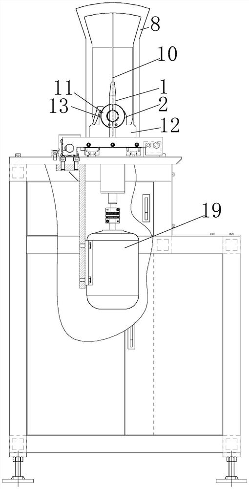
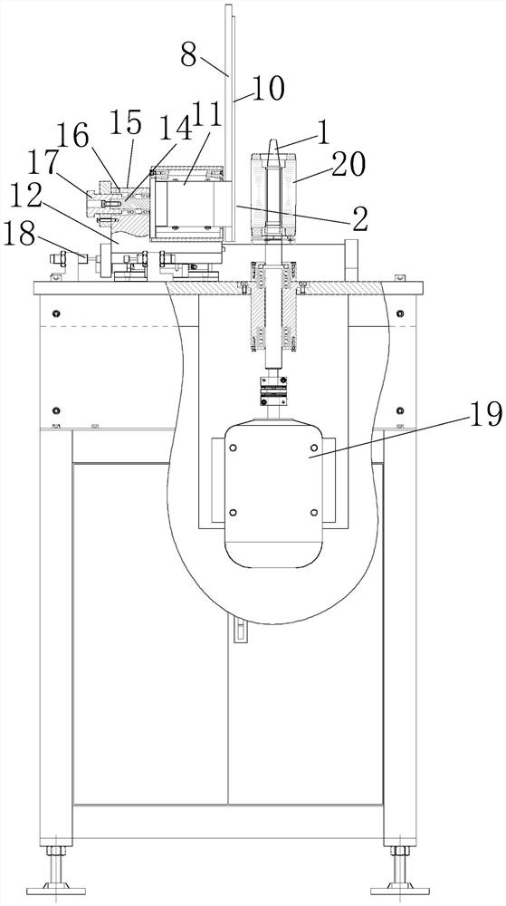
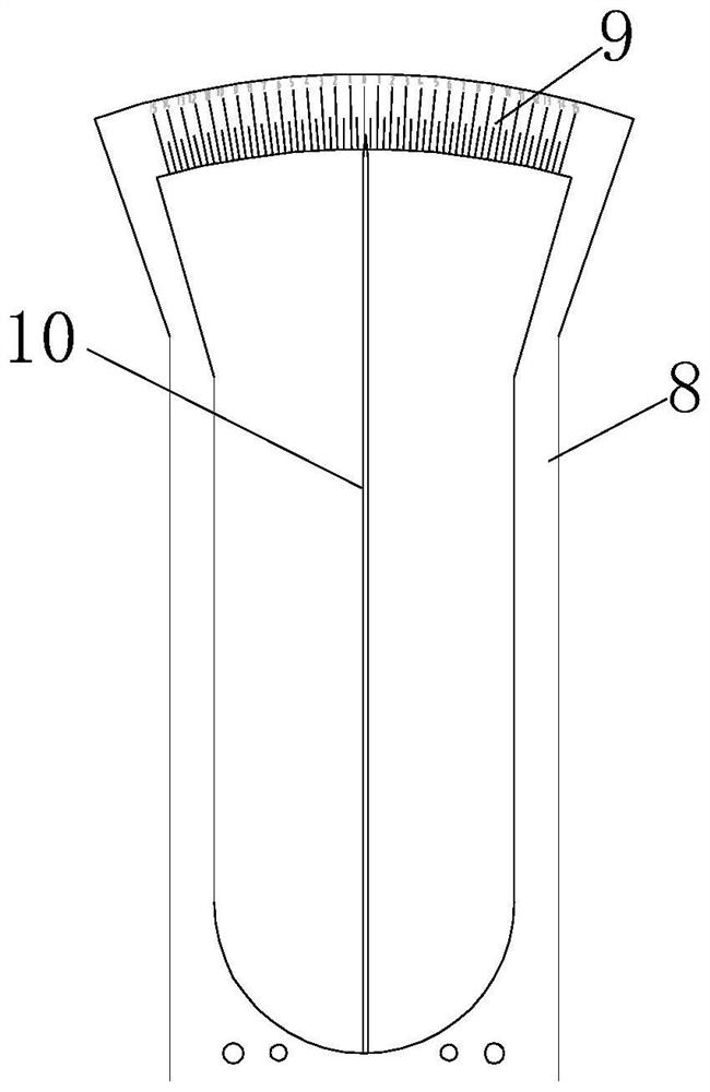
[0037] A rotor aluminum strip detection device disclosed in this embodiment, Figure 1-Figure 4 And as shown, it includes a rotating shaft 1 that drives the rotor to rotate, and one side of the rotating shaft 1 is provided with a stator probe assembly 2 . Figure 4 As shown, the stator probe assembly 2 includes a plurality of iron cores 3, the iron cores 3 are provided with notches 4, each of the iron cores 3 is aligned and stacked, and the aligned notches 4 form a notch channel 5, and the slots The slot 5 can be angularly aligned with the standard inclined slot 21 of the rotor 20 to be tested. The slot slot 5 is provided with a magnet 6, and the magnet 6 faces the slot slot 5. The stacked iron cores 3 are wound with induction coils. The receiving line 7 of the electromotive force is directed towards the magnet 6 .
[0038] The iron core sheet 3 is used to form the slot channel 5. The slot channel 5 is convenient for the magnetic field lines in the magnet 6 to be transmitted ...
Embodiment 2
[0048] This embodiment discloses the detection method of the rotor aluminum bar, Figure 1-Figure 4 As shown, using the rotor aluminum strip detection device described in Embodiment 1, the detection method includes the following steps:
[0049] S1. Insert the rotor 20 to be tested on the rotating shaft 1, so that the notch channel 5 of the stator side head assembly faces the side of the rotor to be tested 20;
[0050] S2. Adjust the inclination angle of the slot channel 5 in the stator side head assembly to align it with the standard inclined slot 21 of the rotor 20 to be tested;
[0051] S3, connecting the receiving line 7 to the signal receiver, driving the rotating shaft 1 to rotate and driving the rotor 20 to be tested to rotate;
[0052] S4, the magnetic field line generated by the magnet 6 in the iron core 3 and the inclined slot 21 in the rotor 20 to be tested have a cutting action, and the receiving line 7 collects the induced electromotive force energy generated by t...
PUM
 Abstract
Description
Claims
Application Information
 - R&D
- Intellectual Property
- Life Sciences
- Materials
- Tech Scout
- Unparalleled Data Quality
- Higher Quality Content
- 60% Fewer Hallucinations
Browse by: Latest US Patents, China's latest patents, Technical Efficacy Thesaurus, Application Domain, Technology Topic, Popular Technical Reports.
© 2025 PatSnap. All rights reserved.Legal|Privacy policy|Modern Slavery Act Transparency Statement|Sitemap|About US| Contact US: help@patsnap.com


