
Measurement system and measurement method for optical fibre morphology

A measurement system and optical fiber technology, applied in the field of measurement, can solve the problems of reducing accuracy, unable to measure quickly, and consuming time

Inactive Publication Date: 2014-05-21
XIDIAN UNIV
View PDF8 Cites 1 Cited by
  • Summary
  • Abstract
  • Description
  • Claims
  • Application Information

AI Technical Summary

Problems solved by technology

For example, direct measurement using a microscope requires the microscope to focus on one end face of the fiber, move the crosshair in the side eyepiece so that it intersects each edge line of the fiber, and then record the readings. This method not only consumes a lot of time, but also suffers from The limit of error caused by the operator's subjective determination of the fiber boundary
Another example is the forward or backward scattering interferometry, which uses the laser beam as the incident light to irradiate the optical fiber vertically, so that the scattered light interferes, observes and measures the interference fringes of the coherent light, and obtains the mathematical model of the optical fiber according to the scattered light pattern analysis method. The theory of the method is relatively mature, but the measurement accuracy is low, and the practical application is of little significance
[0004] The main disadvantage of these methods is that they all require human judgment, which reduces the accuracy, and it takes a lot of time to measure quickly.

Method used


Image

  • Measurement system and measurement method for optical fibre morphology
  • Measurement system and measurement method for optical fibre morphology
  • Measurement system and measurement method for optical fibre morphology

Examples


Embodiment Construction

[0058] The structure of the fiber shape measurement system of the present invention and the detailed process of measuring fiber shape parameters will be clearly and completely described below in conjunction with the accompanying drawings.

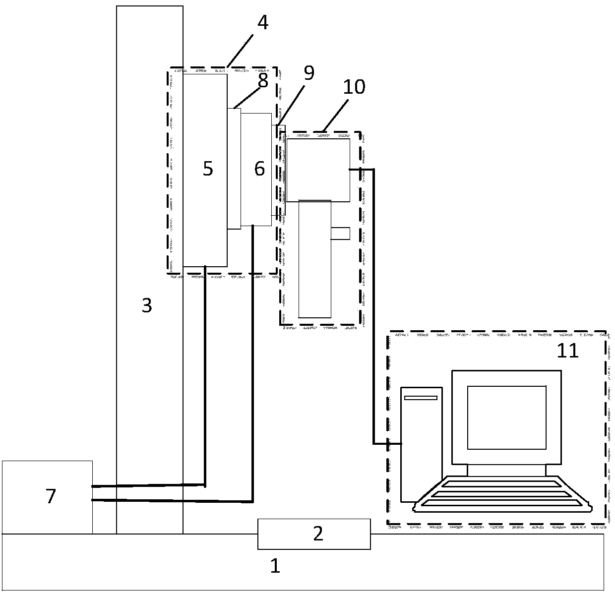
[0059] refer to figure 1 , The measurement system of the present invention includes: a stage 1, a structural support 3, a translation platform 4, a vertical electric translation platform 5, a horizontal electric translation platform 6, a controller 7, a first plane adapter plate 8, a second plane translation Connection board 9, shooting system 10 and image processor 11.

[0060] The displacement platform 4 includes a vertical electric displacement platform 5 and a horizontal electric displacement platform 6, the vertical electric displacement platform 5 is fixed on the structural support 3, and the horizontal electric displacement platform 6 is fixed on the vertical electric displacement platform through the first plane adapter plate 8 On ...


PUM


Abstract

The invention discloses a measurement system and a measurement method for optical fibre morphology, which are mainly used for solving the problems of the need of human judgment, low accuracy, the need of consumption for lots of time, and incapacity of rapidly measuring in the existing measurement method. The measurement system comprises an objective table (1), a structure support (3), a displacement table (4), a controller (7), a shooting system (10) and an image processor (11). During a measurement, the measured optical fibre is fixed on the clamping groove of the objective table, the displacement table is controlled to move by the controller, then the shooting system is driven to carry out focusing shooting on the optical fibre for many times to acquire an optical fibre image, and the optical fibre image is conveyed to the image processor to calculate, so as to obtain the morphology parameters of the optical fibre, that is, an axial length, an end surface radial diameter, the diameter of the middle thinnest part, and a surface inclination angle. According to the measurement system and the measurement method disclosed by the invention, a human judgment is not needed, and the measurement accuracy and measurement speed are improved by evaluating the average value by measuring for many times and automatically processing the image by the image processor; and the measurement system and the measurement method can be used for screening qualified optical fibres products and improving the performances of optical fibre devices.

Description

technical field [0001] The invention belongs to the technical field of measurement, and in particular relates to a measurement system for optical fiber appearance, which can be used to screen out qualified optical fiber products and improve the performance of optical fiber devices. Background technique [0002] As the main material of fiber optic gyro, the shape parameters of optical fiber are related to the functions of optical power distribution, multiplexing / demultiplexing, power coupling and gain flattening. And the performance of the fiber optic gyroscope is critical. [0003] At present, there are many methods for measuring the shape of optical fibers proposed at home and abroad, mainly including: direct measurement method, image shearing method, mechanical contact method, image flip microscope method, rotating mirror offset method, forward scattering method, and backscattering method , CCD non-contact measurement method, etc. For example, direct measurement using a ...

Claims


Application Information

Patent Timeline
IPC IPC(8): G01B11/24
Inventor 邵晓鹏张少辉杜娟王琳
Owner XIDIAN UNIV
Learn More