
Headlamp illumination detection method

An illuminance detection and illuminance technology, which is used in the direction of testing the alignment of automobile headlights, optical instrument testing, measuring devices, etc.

Active Publication Date: 2018-06-22
HANGZHOU ZHEJIANG UNIV SENSING INSTR
View PDF13 Cites 1 Cited by
  • Summary
  • Abstract
  • Description
  • Claims
  • Application Information

AI Technical Summary

Problems solved by technology

At present, the detection and adjustment of the position of the detector is generally performed by emitting a centering laser, judged by manual visual inspection, and then manually adjusted. The detection of the strongest light spot (spot) of the headlight is also realized by combining manual operation and a photometric detector. It is not only time-consuming and labor-intensive, but also not accurate enough

Method used


Image

  • Headlamp illumination detection method

Examples


Embodiment

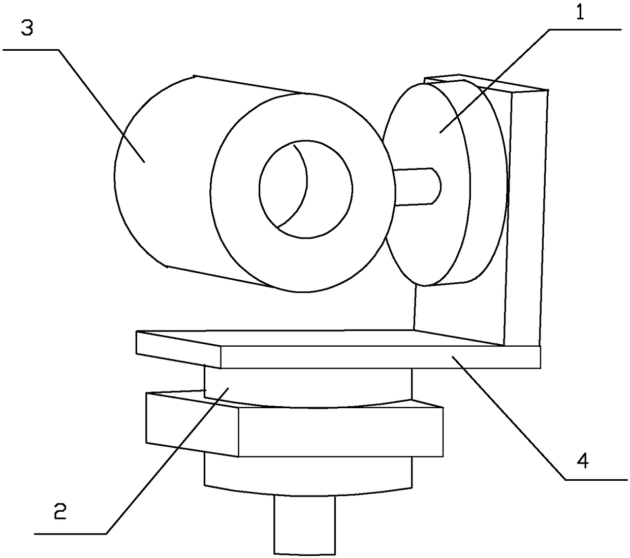
[0027]Embodiment: the headlight illuminance detection method of the present embodiment adopts an illuminance detection device, and the illuminance detection device includes a photometric detector, a main control module, an acquisition module, a display module, a stepping transmission mechanism, a photometric detector, an acquisition module, a display The module and the stepping transmission mechanism are respectively connected with the main control module. The stepping transmission mechanism controls the photometric detector to move in the X direction and the Y direction. The photometric detector adopts a constant temperature photometric detector corrected by V(λ). The transmission mechanism adopts high-precision stepping conveyor belt. The illuminance detection device of this embodiment is installed on the test bench that can be moved to the locomotive track through the guide rail. A digital camera is installed above the photometric detector. The photometric detector is instal...


PUM


Abstract

The invention relates to a headlamp illumination detection method. The method is characterized by carrying out automatic alignment adjusting of a luminosity detector; when the luminosity detector anda locomotive headlamp are in an alignment state, through a stepping transmission mechanism, automatically making the luminosity detector carry out X direction and Y direction stepping shifts, whereina device automatically records each stepping position of the luminosity detector and a headlamp illumination value measured at the stepping position; through calculation, finding the position of the highest headlamp illumination point and determining whether the highest headlamp illumination point is at a standard position; and if the highest headlamp illumination point is not at a standard position, finding an offset direction and an offset distance, and carrying out automatic adjusting subsequently. In the invention, a whole detection and adjusting process is completed automatically by the device, manual determination and operation are not needed, labor saving and time saving are achieved, and accuracy and reliability are high.

Description

technical field [0001] The invention relates to a rail transit headlight illuminance detection technology, in particular to a headlight illuminance detection method. Background technique [0002] For rail transit, such as locomotives and motor vehicles, the headlights on them have standard requirements and need to meet certain technical conditions. The illuminance detection device is a device that detects the center position of the light spot and the irradiation distance of the headlight. At present, before the headlight spot illumination detection device detects the locomotive headlight, the position of the detector needs to be adjusted so that the center point of the detector is located on the reference axis of the headlight, which is called centering, so as to ensure the subsequent illuminance The detection is relatively correct and reliable. At present, the detection and adjustment of the position of the detector is generally performed by emitting a centering laser, ju...

Claims


Application Information

Patent Timeline
Patent Type & Authority Applications(China)
IPC IPC(8): G01M11/06
CPCG01M11/061
Inventor 王建平乔波胡秋红颜平
Owner HANGZHOU ZHEJIANG UNIV SENSING INSTR
Learn More