Method for identifying fractal features of friction boundary of rear cutter face of cutter tooth of high-energy-efficiency milling cutter

A technology of fractal features and identification methods, which is applied in special data processing applications, instruments, complex mathematical operations, etc., and can solve the problems of unquantifiable revealing of dynamic change features and neglect

Pending Publication Date: 2022-05-03
HARBIN UNIV OF SCI & TECH
View PDF0 Cites 1 Cited by
  • Summary
  • Abstract
  • Description
  • Claims
  • Application Information

AI Technical Summary

Problems solved by technology

The information at different positions of the milling cutter tooth friction boundary is ignored, and the dynamic change characteristics of the milling cutter tooth flank friction bounda

Method used


Image

  • Method for identifying fractal features of friction boundary of rear cutter face of cutter tooth of high-energy-efficiency milling cutter
  • Method for identifying fractal features of friction boundary of rear cutter face of cutter tooth of high-energy-efficiency milling cutter
  • Method for identifying fractal features of friction boundary of rear cutter face of cutter tooth of high-energy-efficiency milling cutter

Examples


specific Embodiment approach 1

[0074] Embodiment 1: A method for identifying the fractal characteristics of the frictional boundary of the flank of a high-energy-efficiency milling cutter, which specifically includes the following steps:

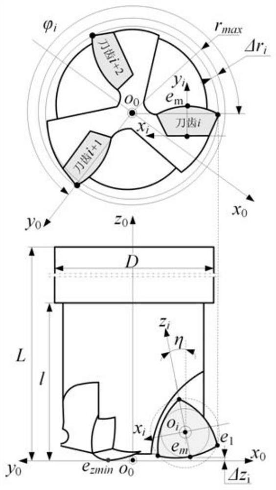
[0075] Step S1, constructing a high-energy-efficiency milling cutter coordinate system and its cutter tooth flank equation;

[0076] Solve the milling cutter and its cutter tooth structure and flank equation to obtain the cutter flank equation and cutter cutting edge equation;

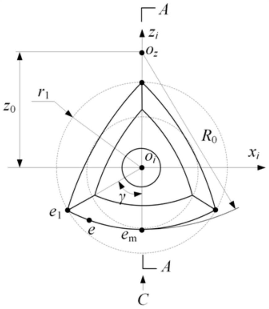
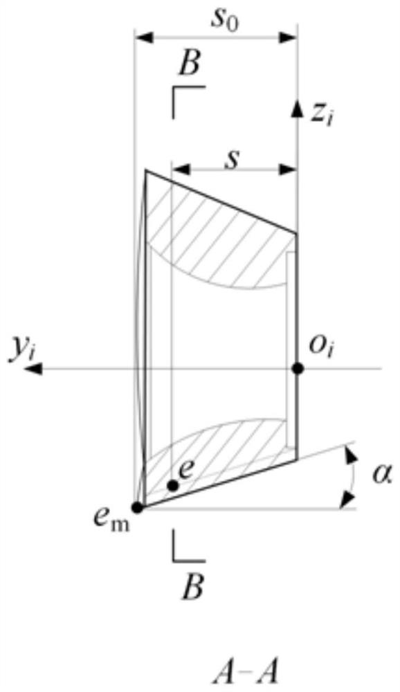
[0077] Step S2, constructing a high-energy-efficiency milling cutter tooth flank friction boundary measurement coordinate system;

[0078] Step S3, solving the fractal characteristic parameters of the friction boundary of the cutter tooth flank;

[0079] Under the high-energy-efficiency milling cutter flank friction boundary measurement coordinate system constructed in step S2, the projection surface of the flank flank is intercepted, the instantaneous friction boundary feature points are extract...

specific Embodiment approach 2

[0208] Specific implementation mode two: the identification method of the fractal characteristics of the friction boundary of the flank of the high-energy-efficiency milling cutter tooth, which also includes the calculation of the cumulative friction boundary of the flank of the milling cutter tooth and its fractal characteristic verification method. The specific implementation method is:

[0209] (1) Identify and characterize the upper boundary curve formed by the maximum friction boundary of instantaneous friction in each cycle of the cutter tooth i when the milling cutter cuts in, cuts in, and cuts out respectively. Figure 35 shown.

[0210] According to the above analysis, the upper boundary of cumulative friction on the flank of milling cutter teeth is shown in Equation (37).

[0211] V s (U)=V s (U,t) (37)

[0212] In formula (37), V s (U,t) is the V coordinate value of the instantaneous friction upper boundary curve on the flank of the milling cutter tooth flank at...

specific Embodiment approach 3

[0229] Specific implementation method three: a method for identifying the fractal characteristics of the friction boundary of the flank of a high-energy-efficiency milling cutter;

[0230] In order to verify the effectiveness and applicability of the fractal characterization and identification method for the flank friction boundary of high-energy-efficiency milling cutters. Design and implement high-energy-efficiency milling cutters. Use the same milling cutters, workpieces, installation methods, cutting methods, and detection methods as those in Scheme 1. Keep the cutting depth and cutting width unchanged. Increase the milling cutter speed and change the tooth error distribution to change the According to the vibration characteristics of milling, the feed per tooth is correspondingly reduced to keep the cutting efficiency constant, and the fractal characteristic parameters of the friction boundary of the cutter tooth flank are calculated. The second scheme is shown in Table 6....


PUM


Abstract

The invention discloses a high-energy-efficiency milling cutter tooth rear cutter face friction boundary fractal feature recognition method, and belongs to the technical field of milling cutter tooth rear cutter face boundary detection and recognition. The method comprises the following steps: S1, constructing a high-energy-efficiency milling cutter coordinate system and a cutter tooth rear cutter surface equation thereof; s2, constructing a friction boundary measurement coordinate system of the rear cutter face of the cutter tooth of the high-energy-efficiency milling cutter; s3, resolving fractal characteristic parameters of the friction boundary of the rear cutter surface of the cutter tooth; s4, representing an instantaneous geometric contact relation between the rear cutter surface of the cutter tooth and the machining transition surface; step S5, constructing instantaneous normal stress, tangential stress and temperature field criteria of the rear cutter surface of the cutter tooth; step S6, constructing a cutter tooth rear cutter surface instantaneous friction boundary feature point criterion; and S7, resolving the dynamic distribution characteristics of the fractal characteristic parameters of the instantaneous friction boundary of the rear cutter surface of the cutter tooth. According to the method, an instantaneous contact relation model of the cutter tooth and the machining transition surface is established, and the problem that an existing method neglects the influence of an instantaneous cutter-workpiece contact relation on the formation of an instantaneous friction boundary of the rear cutter face of the cutter tooth is solved.

Description

technical field [0001] The invention relates to a method for identifying the fractal characteristics of the friction boundary of a cutter tooth flank, and belongs to the technical field of detection and identification of the cutter tooth flank boundary. Background technique [0002] The identification of the fractal characteristics of the flank friction boundary of the high-energy-efficiency milling cutter is an important index to reveal the formation process of the flank friction boundary of the milling cutter and evaluate the friction and wear of the flank. [0003] Establishing a fractal feature recognition method for the flank friction boundary of a high-energy-efficiency milling cutter and revealing its dynamic distribution characteristics can provide guidance for the evolution mechanism of the formation process of the friction boundary of the flank friction boundary of a high-energy-efficiency milling cutter. [0004] There is a method for calculating the friction boun...

Claims


Application Information

Patent Timeline
IPC IPC(8): G06F30/23G06F17/12G06F119/14G06F119/08
CPCG06F30/23G06F17/12G06F2119/14G06F2119/08
Inventor 姜彬季嗣珉赵培轶
Owner HARBIN UNIV OF SCI & TECH
Why Eureka
Try Eureka