
Hydraulic block for electronic brake device of vehicle

An electronic brake and hydraulic block technology, applied in the direction of brake transmission, vehicle sub-unit function, fluid pressure actuation device, etc., can solve the problems of complicated assembly work of the brake system, increased manufacturing cost and weight of the brake system, etc.

Pending Publication Date: 2022-05-06
HYUNDAI MOBIS CO LTD
View PDF5 Cites 1 Cited by
  • Summary
  • Abstract
  • Description
  • Claims
  • Application Information

AI Technical Summary

Problems solved by technology

As a result, there are problems in that the manufacturing cost and weight of the brake system increase, and the assembly work for manufacturing the brake system becomes complicated

Method used


Image

  • Hydraulic block for electronic brake device of vehicle
  • Hydraulic block for electronic brake device of vehicle
  • Hydraulic block for electronic brake device of vehicle

Examples


Embodiment Construction

[0017] The present invention is described more fully hereinafter with reference to the accompanying drawings, in which embodiments of the invention are shown. However, this invention may be embodied in many different forms and should not be construed as limited to the embodiments set forth herein. Rather, these embodiments are provided so that this disclosure is thorough, and will fully convey the scope of the invention to those skilled in the art. In the drawings, the same reference numerals denote the same elements.

[0018] Hereinafter, exemplary embodiments will be described in detail with reference to the accompanying drawings. Regarding the reference numerals assigned to the components in the drawings, the same components will be denoted by the same reference numerals wherever possible even if they are shown in different drawings. Also, in describing the exemplary embodiments, detailed descriptions of well-known related structures or functions will be omitted when it i...


PUM


Abstract

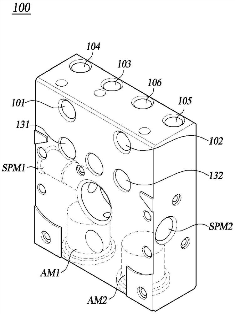
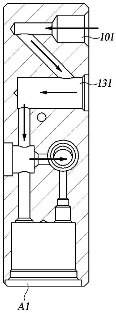
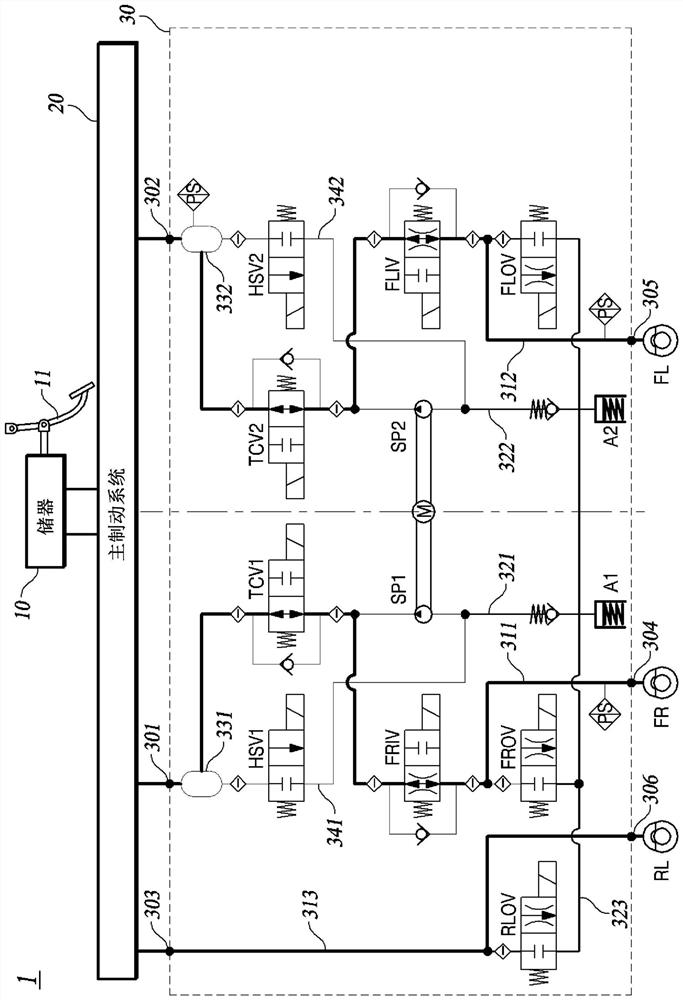
A hydraulic block for an electronic brake device of a vehicle, the hydraulic block comprising: a first input port and a second input port configured to receive brake fluid from a main brake system; at least one oil chamber connected to one of the first input port and the second input port; a first output port and a second output port configured to discharge brake fluid to a plurality of wheel braking devices; a first inlet line configured to connect the first input port and the first output port to each other; a second inlet line configured to connect the second input port and the second output port to each other; a first outlet line branching off from the first inlet line; a second outlet line branching off from the second inlet line; and a valve mounting unit to which a plurality of valves are mounted.

Description

[0001] Cross References to Related Applications [0002] This application claims priority and benefit from Korean Patent Application No. 10-2020-0145117 filed on November 3, 2020, which is hereby incorporated by reference for all purposes as set forth herein. technical field [0003] Exemplary embodiments relate to a hydraulic block for an electronic brake device of a vehicle. Background technique [0004] The statements in this section merely provide background information related to the present disclosure and may not constitute prior art. [0005] When a failure occurs in the main braking system, the autonomously driven vehicle ensures a fail-safe function using an auxiliary braking system disposed between the main braking system and a plurality of wheel braking devices. [0006] A conventional auxiliary brake system performs a dual-channel pressure increase / decrease control operation and a dual-channel pressure decrease control operation. For example, a conventional aux...

Claims


Application Information

Patent Timeline
Patent Type & Authority Applications(China)
IPC IPC(8): B60T8/34B60T13/68B60T8/94
CPCB60T8/346B60T8/341B60T13/686B60T8/94B60T8/368B60T8/343B60T13/141B60T17/04B60T2270/10B60T2270/203B60T2270/402B60T8/4809B60T2201/03B60Y2400/81B60Y2304/05B60Y2304/07B60T15/028F15B13/0814F15B2013/002F15B1/04
Inventor 安成基
Owner HYUNDAI MOBIS CO LTD
Learn More