Supercharge Your Innovation With Domain-Expert AI Agents!

Pressure relief structure of oil pan

A technology of pressure relief structure and oil pan, which is applied in the direction of oil pan, engine lubrication, lubrication indicator device, etc., can solve the problem of large failure risk of oil pan, and achieve the effect of avoiding damage

Pending Publication Date: 2022-05-06
DONGFENG CUMMINS ENGINE
View PDF0 Cites 0 Cited by
  • Summary
  • Abstract
  • Description
  • Claims
  • Application Information

AI Technical Summary

Problems solved by technology

However, under icing conditions, the crankcase pressure will rise above this burst pressure limit, so the conventional oil pan has a greater risk of failure in the case of abnormal cold start in cold regions

Method used


Image

  • Pressure relief structure of oil pan
  • Pressure relief structure of oil pan
  • Pressure relief structure of oil pan

Examples


Embodiment Construction

[0018] In order to make the technical problems, technical solutions and beneficial effects to be solved by the present application clearer, the present application will be further described in detail below in conjunction with the accompanying drawings and embodiments. It should be understood that the specific embodiments described here are only used to explain the present application, and are not intended to limit the present application.

[0019] It should be noted that when an element is referred to as being “fixed” or “disposed on” another element, it may be directly on the other element or be indirectly on the other element. When an element is referred to as being "connected to" another element, it can be directly connected to the other element or indirectly connected to the other element.

[0020] It is to be understood that the terms "length", "width", "top", "bottom", "front", "rear", "left", "right", "vertical", "horizontal", "top" , "bottom", "inner", "outer" and oth...


PUM


Abstract

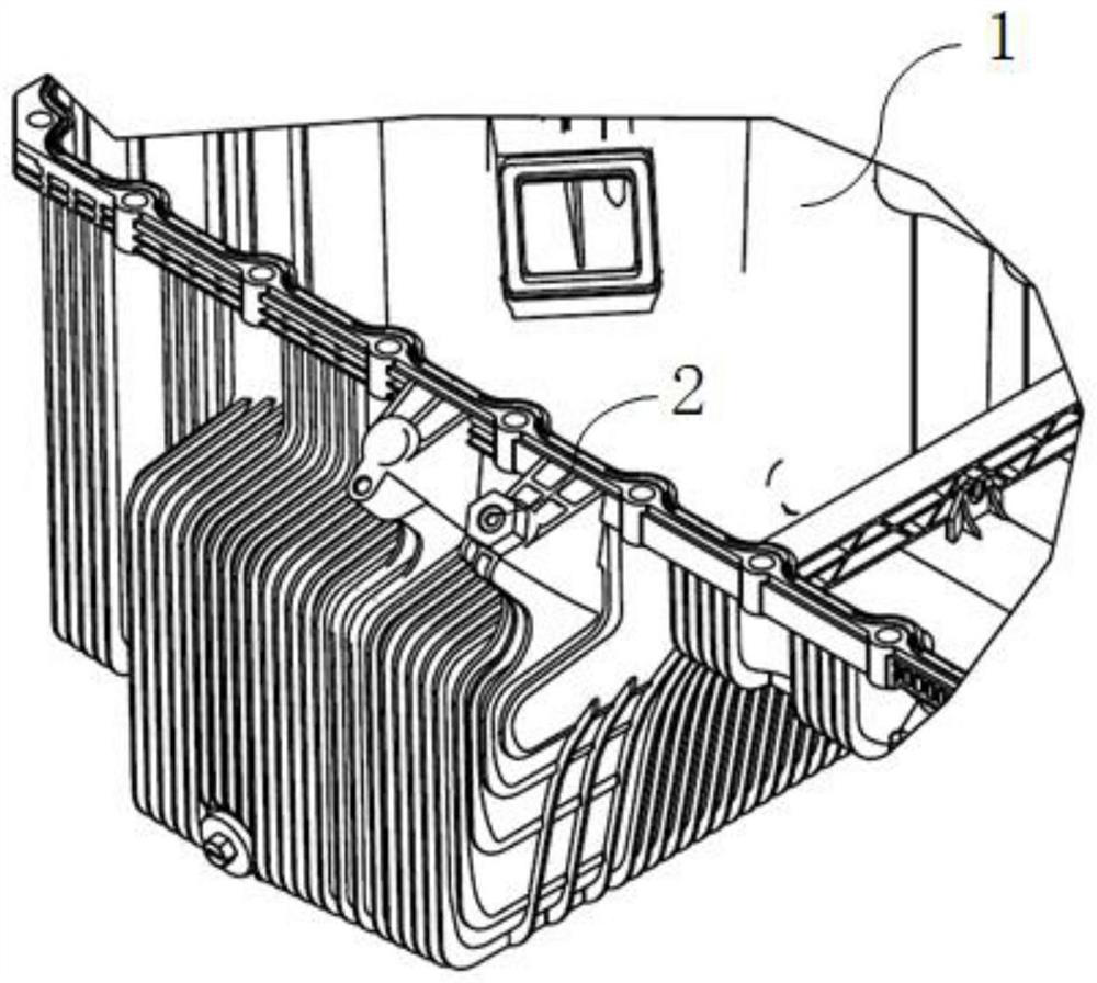
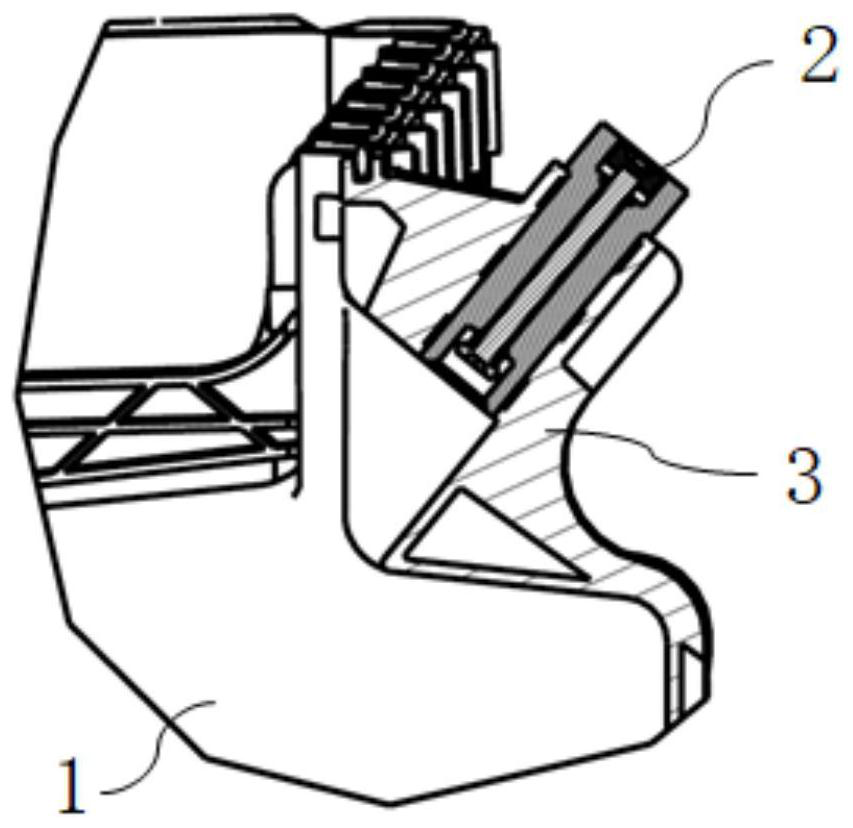
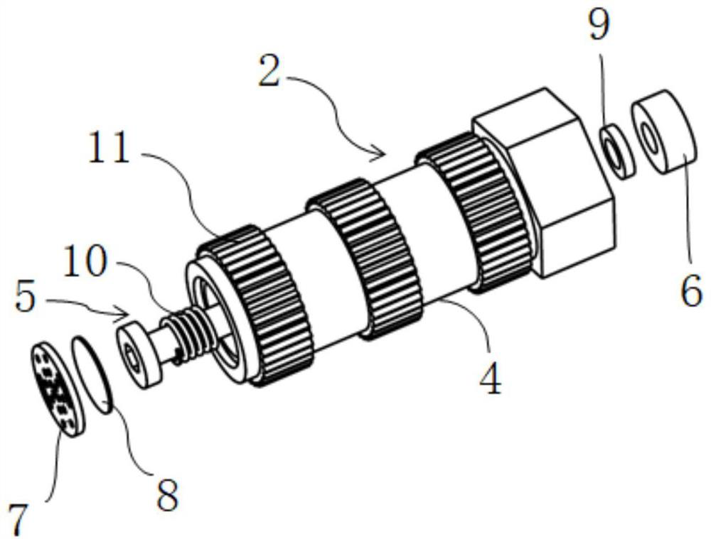
The invention relates to the technical field of engine oil pans, in particular to a pressure relief structure of an oil pan. The oil pan is provided with a pressure release valve on the exhaust side of the engine, the pressure release valve comprises a shell, a valve element push rod, a spring and a sealing cover plate, an air inlet cavity, an exhaust cavity and a valve element assembly cavity are formed in the shell, the valve element assembly cavity is located in the middle section and can be communicated with the air inlet cavity and the exhaust cavity, the air inlet cavity is communicated with the interior of the oil pan, and the valve element push rod is arranged in the valve element assembly cavity in a sliding mode; an airflow gap is formed between the valve element push rod and the wall face of the valve element assembly cavity, a blocking head is arranged at the front end of the valve element push rod, the spring is arranged on the valve element push rod in a sleeving mode and located in the air inlet cavity, one end of the spring makes elastic contact with the blocking head, the other end of the valve element push rod is fixedly connected with the sealing cover plate, and the sealing cover plate makes sealing contact with the bottom face of the exhaust cavity. According to the scheme, through the structure, automatic exhaust can be achieved when the pressure in the cylinder is too large, and damage to the oil pan is effectively avoided.

Description

technical field [0001] The invention relates to the technical field of engine oil pans, in particular to a pressure relief structure of the oil pan. Background technique [0002] The use of natural gas engines in cold regions faces the problem of freezing at cold start. When the respirator freezes, the crankcase pressure will continue to increase, and it is necessary to release the pressure in time. The bursting pressure requirement of the plastic oil sump is greater than 1.5bar, and the actual measurement shows that the oil pan will rupture at about 2.7bar. However, in the case of icing, the crankcase pressure will rise above this burst pressure limit, so the conventional oil sump has a greater risk of failure in the case of abnormal cold start in cold regions. Contents of the invention [0003] The object of the present invention is to address the defects of the prior art and provide a pressure relief structure for the oil pan, which can automatically perform pressure r...

Claims


Application Information

Patent Timeline
Patent Type & Authority Applications(China)
IPC IPC(8): F01M11/00F01M11/10
CPCF01M11/0004F01M11/10
Inventor 黄远博赵增徐丙平卢晓曦
Owner DONGFENG CUMMINS ENGINE
Features
  • R&D
  • Intellectual Property
  • Life Sciences
  • Materials
  • Tech Scout
  • Unparalleled Data Quality
  • Higher Quality Content
  • 60% Fewer Hallucinations
Learn More