
Reflection cup and lamp

A reflective cup and reflective technology, applied in the field of lighting, can solve problems such as unfavorable user visual experience and eye health, affect user reading and writing work, and poor user experience, so as to improve light irradiation to invalid areas and improve ghosting Phenomenon, improve the effect of ghosting

Pending Publication Date: 2022-05-06
宁波公牛光电科技有限公司
View PDF0 Cites 0 Cited by
  • Summary
  • Abstract
  • Description
  • Claims
  • Application Information

AI Technical Summary

Problems solved by technology

The most common type of LED desk lamp is the direct lighting type, which includes a combination of components such as lamp panels, lamp beads, lenses, and reflectors; when desk lamps are used, they are usually placed on the working / writing area on the workbench or desk ( When used in front of the working surface), there are usually the following problems: 1. Part of the light emitted by the light-emitting surface of the desk lamp is irradiated on the area behind the desk lamp, that is, the invalid area outside the working surface, and may also cause glare due to the reflection of the wall; 2. The light emitted from the light-emitting surface of the desk lamp in different directions has different illuminance in different areas of the work surface, which affects the normal reading and writing work of the user.
[0003] Related technologies In order to improve the above problems, the structure of the reflector is adjusted. Although it can improve the problem that the light is irradiated to the invalid area and the intensity is different, it will cause ghosting on the working surface, which is not conducive to the user's visual experience and user experience. Eye health, poor user experience

Method used


Image

  • Reflection cup and lamp
  • Reflection cup and lamp
  • Reflection cup and lamp

Examples


Embodiment Construction

[0035] In order to make the purpose, technical solutions and advantages of the embodiments of the present invention clearer, the technical solutions in the embodiments of the present invention will be clearly and completely described below in conjunction with the drawings in the embodiments of the present invention. Obviously, the described embodiments It is a part of embodiments of the present invention, but not all embodiments. The components of the embodiments of the invention generally described and illustrated in the figures herein may be arranged and designed in a variety of different configurations.

[0036] Accordingly, the following detailed description of the embodiments of the invention provided in the accompanying drawings is not intended to limit the scope of the claimed invention, but merely represents selected embodiments of the invention. Based on the embodiments of the present invention, all other embodiments obtained by persons of ordinary skill in the art wi...


PUM


Abstract

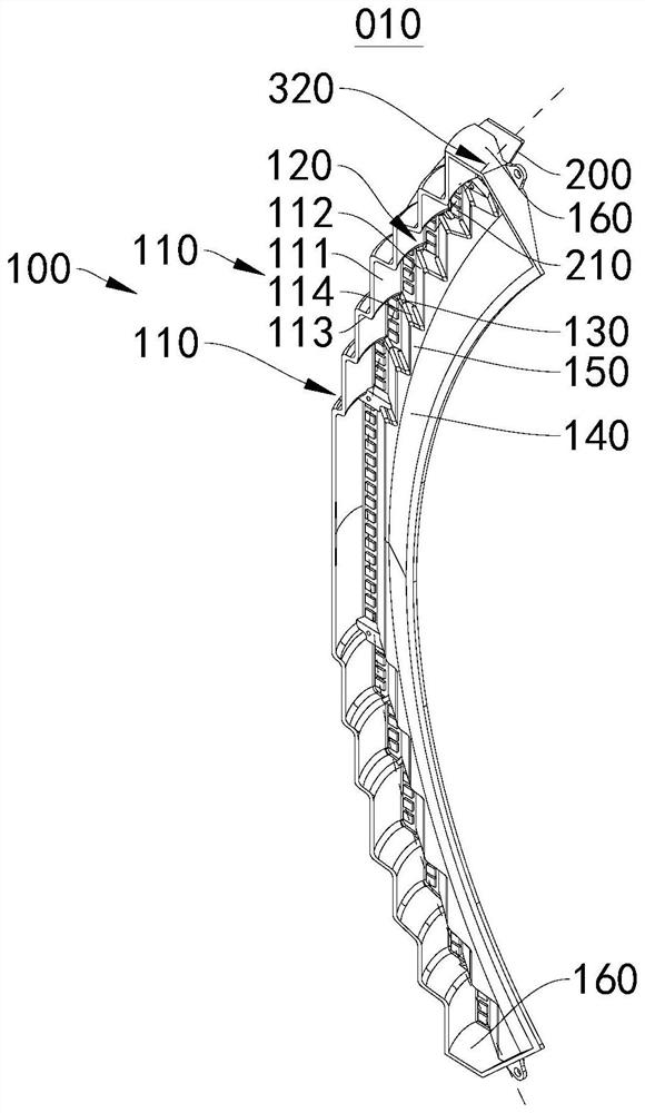
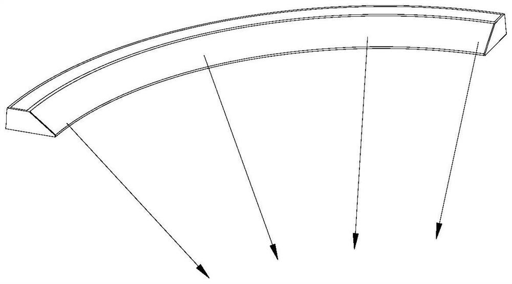
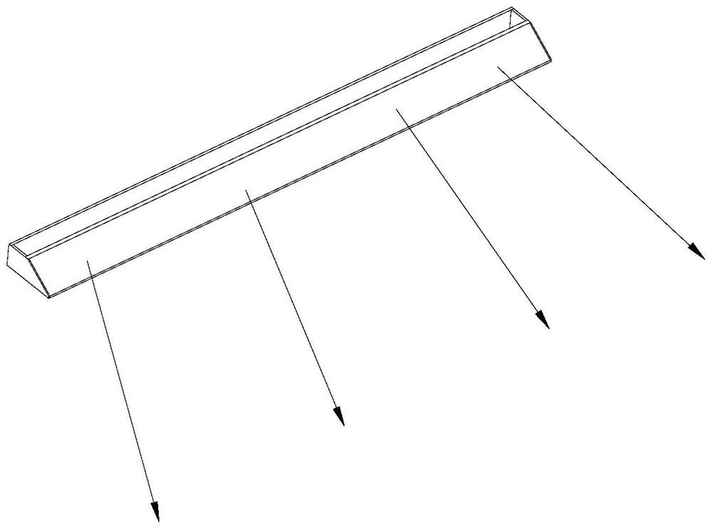
The invention relates to the technical field of illumination, in particular to a reflection cup and a lamp. The lamp comprises a lamp panel and a reflection cup, the lamp panel is provided with lamp beads, the lamp panel is arranged on the reflection cup, the reflection cup comprises a reflection cup body, the reflection cup body comprises a plurality of reflection parts, each reflection part is provided with a reflection cavity, and the reflection parts are sequentially connected and communicated in a staggered mode in the extension direction of a preset arc so that the reflection cavities can be communicated to form a continuous cavity. And the plurality of light reflecting parts are used for reflecting light in the continuous cavity. According to the reflection cup, the problem that light irradiates an invalid area and is different in intensity can be solved, meanwhile, the problem that ghosting is generated on a working face is solved, the visual experience and eye health of a user are facilitated, and the user experience is improved.

Description

technical field [0001] The invention relates to the technical field of lighting, in particular to a reflective cup and a lamp. Background technique [0002] With the development of lighting technology, LEDs have gradually developed into the main lighting products on the market due to their advantages of high efficiency, energy saving and environmental protection; LED lamps include LED table lamps, ceiling lamps and so on. The most common type of LED desk lamp is the direct lighting type, which includes a combination of components such as lamp panels, lamp beads, lenses, and reflectors; when desk lamps are used, they are usually placed on the working / writing area on the workbench or desk ( When used in front of the working surface), there are usually the following problems: 1. Part of the light emitted by the light-emitting surface of the desk lamp is irradiated on the area behind the desk lamp, that is, the invalid area outside the working surface, and may also cause glare d...

Claims


Application Information

Patent Timeline
IPC IPC(8): F21S6/00F21V3/02F21V7/04F21Y115/10
CPCF21S6/003F21V3/02F21V7/04F21Y2115/10
Inventor 朱俊杰侯天宇易博王洪品沈云开
Owner 宁波公牛光电科技有限公司
Learn More