
Horn antenna

A horn antenna and antenna technology, applied in the direction of antennas, waveguide horns, electrical components, etc., can solve the problems of horn antennas with narrow beams, large interference blind spots, and narrow beam widths, and achieve the effect of increasing beam width and improving antenna performance

Pending Publication Date: 2022-05-06
SHENZHEN KUANG CHI HIGH END EQUIP TECH DEV LTD
View PDF0 Cites 0 Cited by
  • Summary
  • Abstract
  • Description
  • Claims
  • Application Information

AI Technical Summary

Problems solved by technology

[0002] In the jammer system, the horn antenna can be used to provide jamming signals to interfere with the target signal, but the beam of the general horn antenna is narrow, the jamming blind area is large, and the jamming effect is poor
[0003] In the prior art, the beam width of the H plane pattern of a horn antenna at 12 GHz is only plus or minus 15°, the beam width is relatively narrow, and the interference blind zone is large

Method used


Image

  • Horn antenna
  • Horn antenna
  • Horn antenna

Examples


Embodiment Construction

[0029] Various embodiments of the invention will be described in more detail below with reference to the accompanying drawings. In the various drawings, the same elements are denoted by the same or similar reference numerals. For the sake of clarity, various parts in the drawings have not been drawn to scale.

[0030] The specific implementation manners of the present invention will be further described in detail below in conjunction with the accompanying drawings and embodiments.

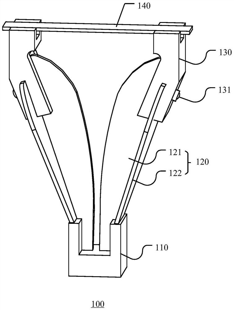
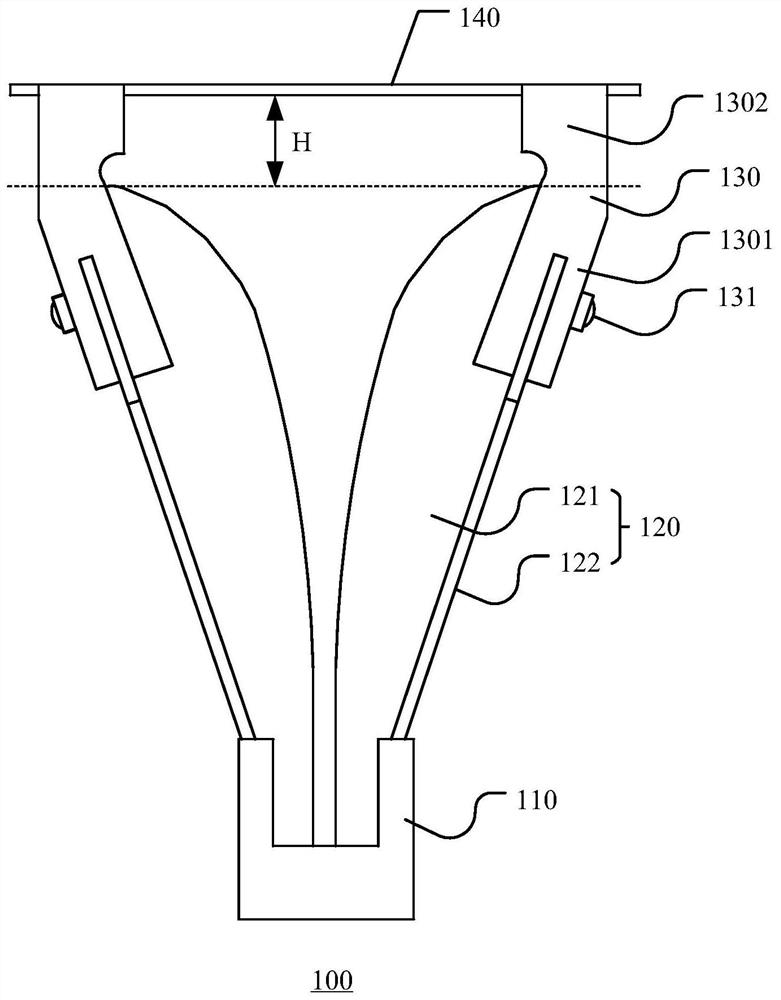
[0031] figure 1 shows a schematic diagram of a three-dimensional structure of a horn antenna according to an embodiment of the present invention, figure 2 A front view of a horn antenna according to an embodiment of the present invention is shown.

[0032] Such as figure 1 with figure 2 As shown, the horn antenna 100 of the embodiment of the present invention includes a back cavity 110, a double ridge horn 120, a fixing member 130 and a metal plate 140, to figure 1 is the direction referenc...


PUM


Abstract

The horn antenna comprises a double-ridge horn antenna body, a metal plate and a fixing piece, the double-ridge horn antenna body is of a mirror symmetry structure, the metal plate is arranged in the opening direction of the double-ridge horn antenna body, and the plate face of the metal plate faces the opening of the double-ridge horn antenna body; according to the horn antenna provided by the invention, the beam width of the horn antenna can be improved, and the antenna performance is improved.

Description

technical field [0001] The invention relates to the technical field of antennas, in particular to a horn antenna. Background technique [0002] In the jammer system, the horn antenna can be used to provide interference signals to interfere with the target signal, but the general horn antenna has a narrow beam, a large interference blind area, and poor interference effect. [0003] In the prior art, a horn antenna has a beam width of only plus or minus 15° in the H-plane pattern at 12 GHz, and the beam width is relatively narrow, and the interference blind zone is large. Contents of the invention [0004] In view of the above problems, the object of the present invention is to provide a horn antenna, thereby increasing the beam width of the horn antenna and improving the performance of the antenna. [0005] According to an aspect of the present invention, a horn antenna is provided, comprising: [0006] A double-ridged horn antenna body with a mirror-symmetrical structure...

Claims


Application Information

Patent Timeline
IPC IPC(8): H01Q13/02H01Q1/36
CPCH01Q13/0275H01Q1/36
Inventor 刘若鹏赵治亚雷硕
Owner SHENZHEN KUANG CHI HIGH END EQUIP TECH DEV LTD
Features
  • Generate Ideas
  • Intellectual Property
  • Life Sciences
  • Materials
  • Tech Scout
  • Unparalleled Data Quality
  • Higher Quality Content
  • 60% Fewer Hallucinations
Learn More