Power amplifier module, control method, terminal and computer storage medium

A power amplifier and low-noise amplifier technology, applied in the field of power amplifier modules, can solve problems such as poor network performance, no effective suppression of coexisting frequencies, and receiver interference

Pending Publication Date: 2022-05-06
GUANGDONG OPPO MOBILE TELECOMM CORP LTD
View PDF0 Cites 0 Cited by
  • Summary
  • Abstract
  • Description
  • Claims
  • Application Information

AI Technical Summary

Problems solved by technology

[0002] Based on the 5G NR trend, Taiwan MediaTek Co., Ltd. (MTK, MediaTek.Inc) has defined a power amplifier module (L-PAMiF, Low noiseamplifier-Power Amplifier Module with integrated filter), among them, the working frequency of n79 is 4400~5000MHz, however, the working frequency of Wireless Fidelity (WiFi, Wireless Fidelity) 5G is 5150~5850MHz, obviously, n79 is very close to the working frequency band of WiFi 5G. This frequency is called the coexistence frequency. In practical applications, this coexistence frequency will cause serious interference to their respective receivers.
[0003] In order to eliminate interference, frequency division multiplexing (FDM, Frequency division multiplexing) schemes or time division multiplexing (TDM, Time division multiplexing) schemes are usually used. However, the above schemes do not effectively suppress the coexistence frequency, resulting in network performance It can be seen that the power amplifier module in the existing RF front-end architecture has a technical problem of poor network performance when suppressing coexistence frequencies

Method used


Image

  • Power amplifier module, control method, terminal and computer storage medium
  • Power amplifier module, control method, terminal and computer storage medium
  • Power amplifier module, control method, terminal and computer storage medium

Examples


Embodiment 1

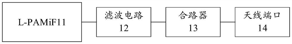
[0034] The embodiment of the present application provides a power amplifier module, figure 1 A schematic structural diagram of an optional power amplifier module provided in the embodiment of the present application, such as figure 1 As shown, the power amplifier module includes: a power amplifier module L-PAMiF11 integrated with a filter and a low noise amplifier and a filter circuit 12;

[0035] One end of the filter circuit 12 is connected with the transceiver port of the first frequency band of L-PAMiF11, the other end of the filter circuit 12 is connected with the input end of the combiner 13, and the output end of the combiner 13 is connected with the antenna port of the first frequency band 14 phase connection;

[0036] The filtering circuit 12 is used for passing signals of a specific frequency band;

[0037] Wherein, the specific frequency band is: the frequency band except the overlapping frequency band in the first frequency band; the overlapping frequency band is...

Embodiment 2

[0085] An embodiment of the present application provides a control method, which is applied to a terminal, and the power amplifier module of the terminal includes: a power amplifier module L-PAMiF integrated with a filter and a low-noise amplifier, a filter circuit, and a switching circuit;

[0086] The first end of the switching circuit is connected to the first transceiver port of the first frequency band of L-PAMiF, the second end of the switching circuit is connected to the other end of the filter circuit, and one end of the filter circuit is connected to the second transceiver port of the first frequency band. Connecting, the third end of the switching circuit is connected to the input end of the combiner, and the output end of the combiner is connected to the antenna port of the first frequency band; Figure 7 It is a schematic flowchart of an optional control method provided by the embodiment of the present application, which is applied to the above-mentioned terminal. R...

Embodiment 3

[0105] Figure 8 Schematic diagram of the structure of a terminal provided in the embodiment of this application Figure 1 ,like Figure 8 As shown, the embodiment of the present application provides a terminal, and the power amplifier module of the terminal includes: a power amplifier module L-PAMiF integrated with a filter and a low noise amplifier, a filter circuit and a switching circuit; the first end of the switching circuit It is connected with the first transceiver port of the first frequency band of the L-PAMiF, the second end of the switching circuit is connected with the other end of the filter circuit, one end of the filter circuit is connected with the second transceiver port of the first frequency band, and the switching circuit The third end of the combiner is connected to the input end of the combiner, and the output end of the combiner is connected to the antenna port of the first frequency band; it also includes: an acquisition module 81 and a control module...


PUM


Abstract

The embodiment of the invention discloses a power amplifier module. The power amplifier module comprises a power amplifier module L-PAMiF and a filter circuit, wherein the power amplifier module L-PAMiF is integrated with a filter and a low-noise amplifier; one end of the filter circuit is connected with a receiving and transmitting port of a first frequency band of the L-PAMiF, the other port of the filter circuit is connected with the input end of the combiner, the output end of the combiner is connected with an antenna port of the first frequency band, and the filter circuit is used for allowing a signal of a specific frequency band to pass through. The embodiment of the invention further provides a control method, a terminal and a computer storage medium.

Description

technical field [0001] The present application relates to the power amplifier module technology in the radio frequency front-end architecture, in particular to a power amplifier module, a control method, a terminal and a computer storage medium. Background technique [0002] Based on the 5G NR trend, Taiwan MediaTek Co., Ltd. (MTK, MediaTek.Inc) has defined a power amplifier module (L-PAMiF, Low noiseamplifier-Power Amplifier Module with integrated filter), among them, the working frequency of n79 is 4400~5000MHz, however, the working frequency of Wireless Fidelity (WiFi, Wireless Fidelity) 5G is 5150~5850MHz, obviously, n79 is very close to the working frequency band of WiFi 5G. This frequency is called the coexistence frequency. In practical applications, this coexistence frequency will cause serious interference to their respective receivers. [0003] In order to eliminate interference, a frequency division multiplexing (FDM, Frequency division multiplexing) scheme or a ...

Claims


Application Information

Patent Timeline
IPC IPC(8): H04B1/401H04B1/40H03F3/24
CPCH04B1/401H04B1/40H03F3/24
Inventor 张亭仝林
Owner GUANGDONG OPPO MOBILE TELECOMM CORP LTD
Why Eureka
Try Eureka