Time synchronization method and device, electronic equipment and storage medium

A technology for synchronizing reports and time. It is applied in electrical components, time division multiplexing systems, and multiplexing communications. It can solve problems such as poor accuracy, and achieve the effect of improving the accuracy of time synchronization and reducing the scope of time calculation.

Pending Publication Date: 2022-05-06
上海思源弘瑞自动化有限公司
View PDF0 Cites 0 Cited by
  • Summary
  • Abstract
  • Description
  • Claims
  • Application Information

AI Technical Summary

Problems solved by technology

In the prior art, when synchronizing, the time of the NTP client is modified to: time at T2 + one-way transmission delay (the time D2 required for the NTP server to receive the response from the NTP server to receive the response, due to D2 cannot be obtained accurately, but D1+D2 can be calculated, and (D1+D2) / 2 can be used instead of D2). The premise of this client / server mode time synchronization method is that it is assumed that the request sent from the NTP client is received by the NTP server The time D1 and time D2 required by the request are equal. However, in fact, there is a difference between time D1 and time D2, and the accuracy of time synchronization depends on the degree to which time D1 and time D2 are equal. The closer time D1 and time D2 are, the better The higher the accuracy of time, the greater the deviation between time D1 and time D2, and the worse the accuracy of time synchronization

Method used


Image

  • Time synchronization method and device, electronic equipment and storage medium
  • Time synchronization method and device, electronic equipment and storage medium
  • Time synchronization method and device, electronic equipment and storage medium

Examples


Embodiment 1

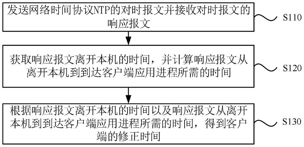
[0029] figure 1 It is a flowchart of a time synchronization method provided by Embodiment 1 of the present invention. This embodiment is applicable to the time synchronization situation in the client and server modes. This method can be executed by the time synchronization device in the embodiment of the present invention. The device can be realized by means of software and / or hardware, and integrated into electronic equipment, wherein the electronic equipment mainly refers to an NTP client. Such as figure 1 As shown, the method specifically includes the following steps:

[0030] S110. Send a time synchronization message of the network time protocol NTP and receive a response message of the time synchronization message.

[0031] Among them, the client sends the time synchronization message, the server receives the time synchronization message and sends a response message, and the client receives the response message. During this process, the time synchronization can be perfo...

Embodiment 2

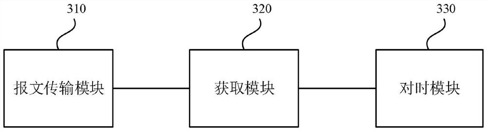
[0080] image 3 It is a schematic structural diagram of a time synchronization device provided by Embodiment 2 of the present invention. This embodiment is applicable to the time synchronization situation in the client and server modes, the device can be implemented in software and / or hardware, and the device can be integrated in any device that provides time synchronization functions, such as image 3 As shown, the time synchronization device specifically includes: a message transmission module 310 , an acquisition module 320 and a time synchronization module 330 .

[0081] A message transmission module 310, configured to send a network time protocol timed message and receive a response message to the timed message;

[0082] An acquisition module 320, configured to acquire the time when the response message leaves the machine, and calculate the time required for the response message to arrive at the client application process from leaving the machine;

[0083] The time sync...

Embodiment 3

[0103] Figure 4 It is a schematic structural diagram of an electronic device provided by Embodiment 3 of the present invention. Figure 4 A block diagram of an electronic device 412 suitable for implementing embodiments of the invention is shown. Figure 4 The electronic device 412 shown is only an example, and should not limit the functions and scope of use of this embodiment of the present invention. Device 412 is a typical time-keeping enabled computing device.

[0104] Such as Figure 4 As shown, electronic device 412 takes the form of a general-purpose computing device. Components of the electronic device 412 may include, but are not limited to: one or more processors 416, a storage device 428, and a bus 418 connecting different system components (including the storage device 428 and the processor 416).

[0105] Bus 418 represents one or more of several types of bus structures, including a memory bus or memory controller, a peripheral bus, an accelerated graphics por...


PUM


Abstract

The embodiment of the invention discloses a time synchronization method and device, electronic equipment and a storage medium. The method comprises the following steps: sending a time synchronization message of a network time protocol (NTP) and receiving a response message of the time synchronization message; obtaining the time when the response message leaves the local machine, and calculating the time required by the response message from leaving the local machine to arriving at the client application process; and obtaining the correction time of the client according to the time when the response message leaves the local machine and the time required by the response message from leaving the local machine to reaching the application process of the client. Compared with the prior art, the time calculation range of sending the time synchronization message from the client to the server and sending the response message from the server to the client is narrowed; the influence of the random waiting time of the message from the kernel of the client and the server to the application on the transmission delay (the message has random delay from the kernel LOCALIN point to the application and from the application to the LOCALOUT point) is eliminated, so that the time synchronization precision is improved.

Description

technical field [0001] Embodiments of the present invention relate to the technical field of time synchronization, and in particular, to a time synchronization method, device, electronic equipment, and storage medium. Background technique [0002] With the continuous emergence of computer network applications, the problem of computer time synchronization becomes more and more important. Network Time Protocol (Network Time Protocol, NTP) is a protocol for synchronizing computer time, which is used for time synchronization between distributed time servers and clients. It can provide high-precision time correction, and can carry authentication codes for identity authentication and integrity protection to prevent malicious protocol attacks. The purpose of using NTP is to synchronize the clocks of all devices with clocks in the network, so that the clocks of all devices in the network are consistent, so that devices can provide multiple applications based on a unified time. [...

Claims


Application Information

Patent Timeline
Patent Type & Authority Applications(China)
IPC IPC(8): H04J3/06
CPCH04J3/0667
Inventor 顾玉杰徐柳茂王凯侍昌江
Owner 上海思源弘瑞自动化有限公司
Why Eureka
Try Eureka