

Wooden building beam column painting equipment
A technology for wooden buildings and beams and columns, applied in the direction of spraying devices, etc., can solve the problems of affecting the appearance of beams and columns, labor-intensive, uneven painting, etc., and achieve the effect of saving manpower
- Summary
- Abstract
- Description
- Claims
- Application Information
AI Technical Summary
Problems solved by technology
Method used
Image

Examples
Embodiment 1
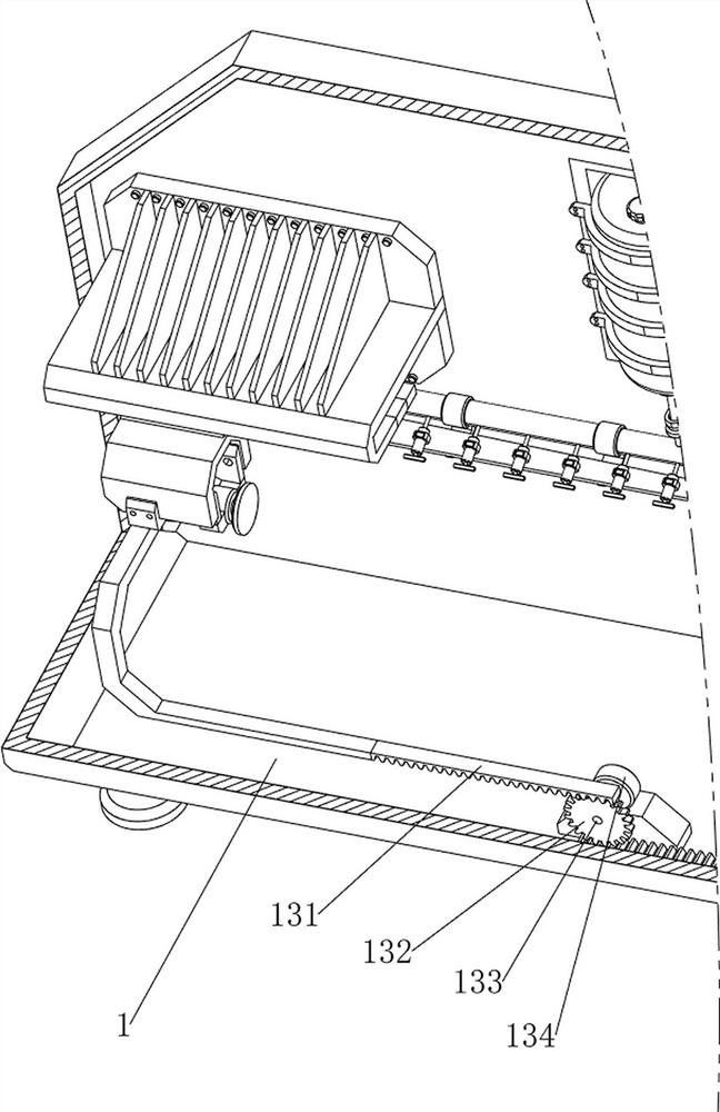
[0042] A wooden building beam and column painting equipment, now refer to Figure 1-4 , including a box body 1, a paint box 2, a first fixing frame 3, a paint pipe 4, a paint spray head 5, a paint baffle plate 6, a diversion tube 7, a protection mechanism 8, a painting mechanism 9 and a fixing mechanism 10, the box body 1. There are six first fixing frames 3 welded on the inner rear part of the box body 1. The lower side of the inner rear part of the box body 1 is provided with a paint box 2. The paint box 2 is used to hold paint. The upper side of the paint box 2 is threadedly provided with a box cover, six Paint pipes 4 are connected between the first fixed frames 3, and fifteen paint spraying heads 5 are evenly arranged between the front sides of the six first fixed frames 3, and the paint spraying heads 5 are connected with the paint pipes 4, and the paint box 2 is connected with the paint pipes 4. There is a guide tube 7 connected between them, the guide tube 7 passes thr...
Embodiment 2
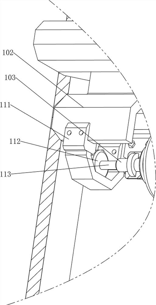
[0048] On the basis of embodiment 1, now refer to Figure 13 , also includes a rotating mechanism 11, the rotating mechanism 11 includes a second fixed frame 111, a second motor 112 and a first rotating shaft 113, the lower side of the first sliding frame 102 is fixed with the second fixed frame 111 by bolts, the second fixed frame The upper side of the frame 111 is fixedly connected with the second motor 112 by bolts, the output shaft of the second motor 112 is connected with the first rotating shaft 113 , and the first rotating shaft 113 is connected with the first extruding plate 103 .
[0049] now refer to Figure 14-17 , also includes a support mechanism 12, the support mechanism 12 includes a first support frame 121, a fourth guide frame 1211, a second slide bar 122, a third spring 123, a second support frame 124, a third slide bar 125, a wedge block 126, the fourth spring 127, the connection block 128 and the pressure rod 129, the second support frame 124 is fixedly co...
PUM
 Abstract
Description
Claims
Application Information