
Automatic welding root and welding pipe orifice windproof device for long oil and gas conveying pipeline

A windproof device, oil and gas transportation technology, applied in the direction of auxiliary devices, welding equipment, auxiliary welding equipment, etc., can solve the problems of delay in welding progress, decrease in connection effect, decrease in welding effect, etc., and achieve the effect of saving deployment time

Pending Publication Date: 2022-05-10
武汉临宸科技有限公司
View PDF0 Cites 0 Cited by
  • Summary
  • Abstract
  • Description
  • Claims
  • Application Information

AI Technical Summary

Problems solved by technology

[0003] However, in the existing technology, the existing long-distance oil and gas pipelines are generally deployed in relatively open outdoor areas, and the overall length and size are longer and larger than ordinary pipelines. It can only be used when the pipes are welded together. When welding in an open area, it may be affected by the wind. If the wind level is small, it will not affect the welding effect. When the wind level reaches a certain level, it will Seriously affect the normal welding of the pipeline, because the welding is generally achieved by heating, the strong wind will cause the air flow speed near the pipeline to be too fast, and it is easy to quickly extract the heat from the welding place, which will lead to the welding effect Decrease, may lead to a decline in the final connection effect, and then delay the normal welding progress

Method used


Image

  • Automatic welding root and welding pipe orifice windproof device for long oil and gas conveying pipeline
  • Automatic welding root and welding pipe orifice windproof device for long oil and gas conveying pipeline
  • Automatic welding root and welding pipe orifice windproof device for long oil and gas conveying pipeline

Examples


Embodiment 1

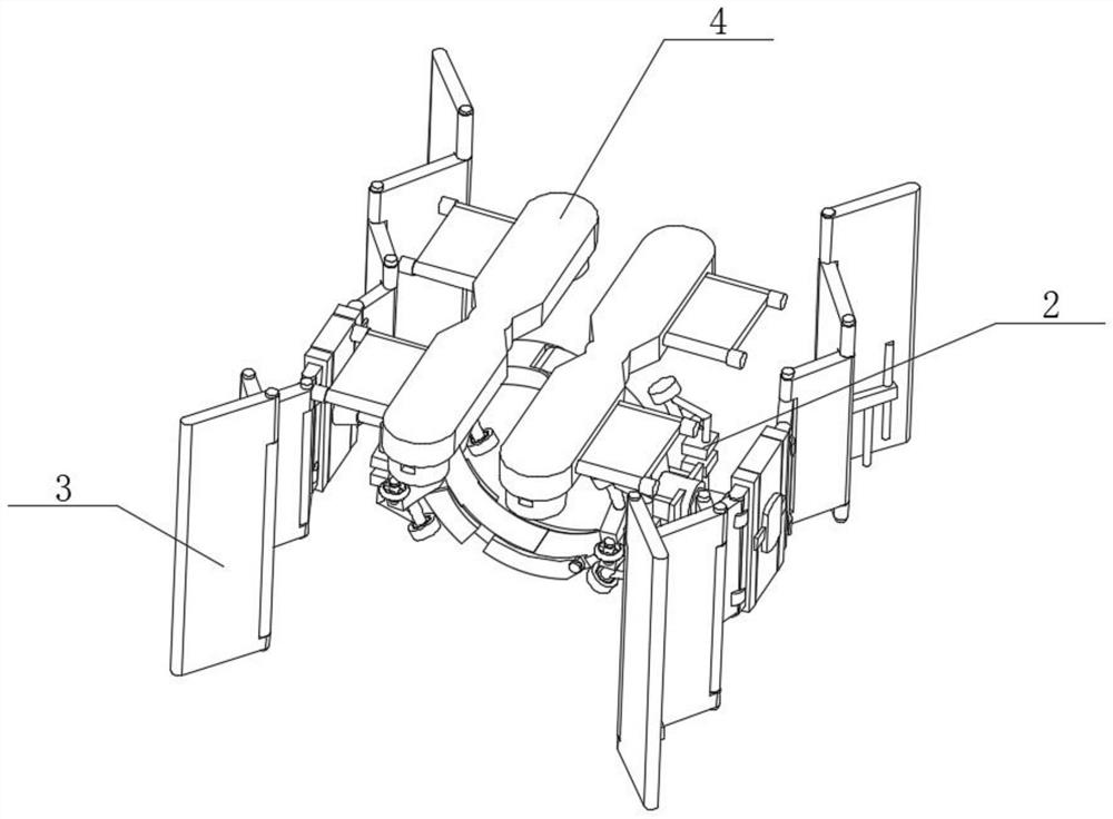
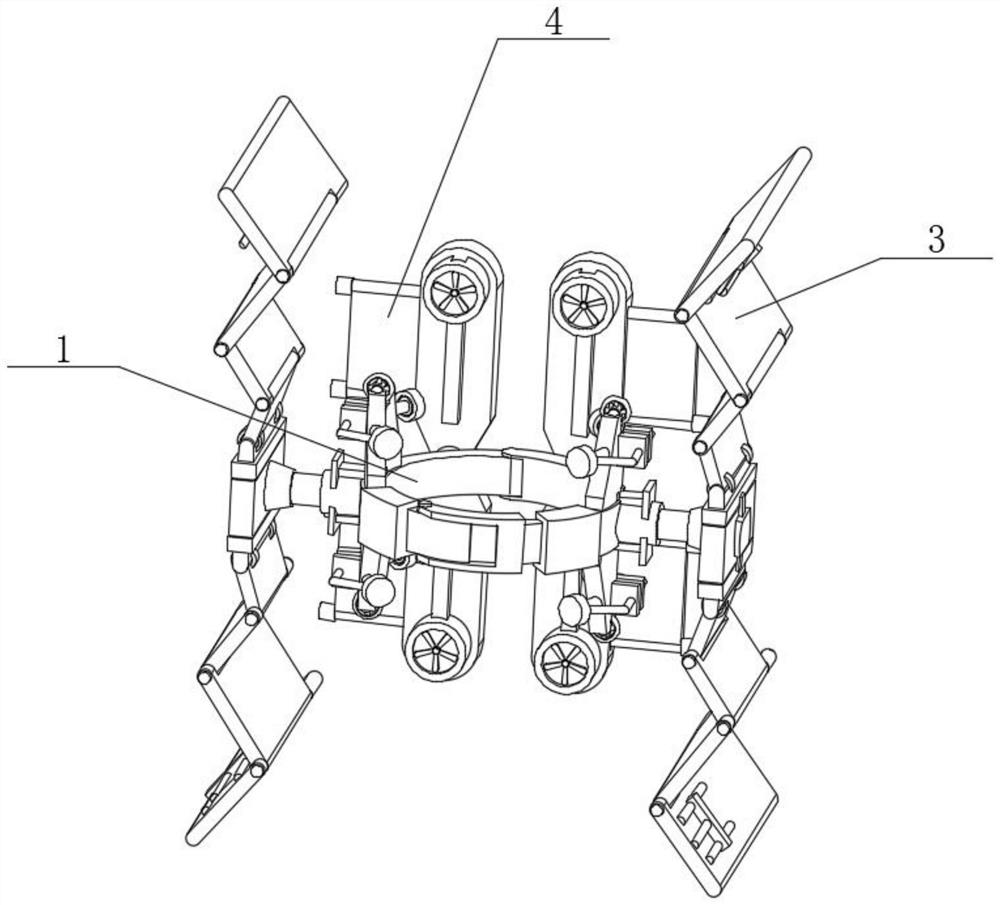
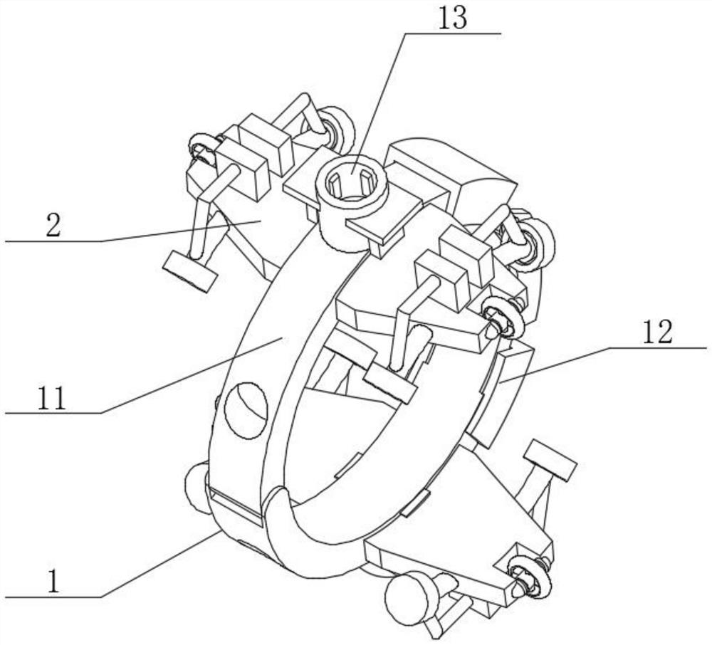
[0050] Such as figure 1 , figure 2 , image 3 and Figure 4 As shown, the present invention provides a technical solution: a long-distance oil and gas pipeline automatic root welding pipe mouth windproof device, including a pipeline butt joint device 1, a moving device 2, a side protection device 3 and a top absorbing device 4, and the moving device 2 is installed on the On both sides of the pipe butt joint device 1, one end of the side guard 3 is connected inside the pipe butt joint device 1, the bottom of the top absorber 4 is connected to the top of the pipe butt joint device 1, and the side guard 3 is located on both sides of the pipe butt joint device 1 , the mobile device 2 is located between the pipe butt joint device 1 and the side protection device 3, the pipe butt joint device 1 includes a pipe clamping structure 11, a locking structure 12, a docking round pipe 13 and a lifting table 14, the two ends of the locking structure 12 are connected to the pipe clamp The...

Embodiment 2

[0053] Such as Figure 4 As shown, the pipe clamping structure 11 includes an arc-shaped rotating panel 111 and a clamping arc-shaped plate 112. One end of the clamping arc-shaped plate 112 is rotatably connected to one end of the arc-shaped rotating panel 111. The locking structure 12 includes a docking port 121, a locking The buckle 122 and the movable hasp 123, the docking port 121 is installed on one end of the locking buckle 122, the other end of the docking port 121 is movably connected with the pipe clamping structure 11, the locking buckle 122 is provided with two, and the movable hasp 123 is installed On the top of one of the locking gussets 122 , the other end of the movable hasp 123 is connected to the inside of the other locking gusset 122 .

[0054] In this embodiment, the arc-shaped rotating panel 111 expands its internal diameter by rotating with the clamping arc-shaped plate 112, so as to be deployed on the oil pipeline for use, and after the deployment is comp...

Embodiment 3

[0056] Such as figure 1 , figure 2 , image 3 , Figure 5 and Figure 6 As shown, the mobile device 2 includes a movable bearing panel 21, the top of the movable bearing panel 21 is provided with a reinforcing support plate 22, and one end of the movable bearing panel 21 is provided with a groove 24, and the inside of the groove 24 is provided with a first roller 25. Both sides of the load-bearing panel 21 are provided with auxiliary rollers 26, an elastic strut 23 is arranged between the auxiliary roller 26 and the movable load-bearing panel 21, and one end of the elastic strut 23 is connected to the inside of the movable load-bearing panel 21, and the elastic strut 23 The other end is connected to the inside of the reinforcement support plate 22 , the other end of the movable bearing panel 21 is connected to the outer wall of the pipe clamping structure 11 , and the lifting platform 14 is located at the intersection of the movable bearing panel 21 and the pipeline clampi...


PUM


Abstract

The invention provides an automatic welding root and welding pipe orifice windproof device for a long oil and gas conveying pipeline, and relates to the technical field of pipeline welding, the automatic welding root and welding pipe orifice windproof device comprises a pipeline butt joint device, moving devices, side protection devices and a top absorption device, the moving devices are installed on the two sides of the pipeline butt joint device, and the top absorption device is installed on the top of the pipeline butt joint device; one end of each side protection device is connected to the interior of the pipeline butt joint device, the bottom of the top absorption device is connected to the top of the pipeline butt joint device, and the side protection devices are located on the two sides of the pipeline butt joint device. According to the pipeline butt-joint device, the whole pipeline butt-joint device can be driven to move in the direction of an oil conveying pipeline through the moving device, so that the side face protection device and the top absorption device can slide on the pipeline, and therefore when welding is conducted in different places, the pipeline butt-joint device does not need to be disassembled and then installed; and the deployment time of the whole device can be effectively saved, so that the normal welding progress of the pipeline is prevented from being delayed.

Description

technical field [0001] The invention relates to the technical field of pipeline welding, in particular to a windproof device for automatic root welding of long-distance oil and gas pipelines. Background technique [0002] Oil pipelines (also called pipelines, pipelines) are composed of oil pipes and their accessories, and are equipped with corresponding oil pump units according to the needs of the process flow, designed and installed as a complete pipeline system for the completion of oil loading and unloading and transportation Task, the oil pipeline system, that is, the pipeline system used to transport oil and petroleum products, is mainly composed of oil pipelines, oil stations and other auxiliary related equipment. It is one of the main equipment in the oil storage and transportation industry and the most As the main transportation equipment, compared with the railway and highway oil transportation, which are also land transportation methods, pipeline oil transportation...

Claims


Application Information

Patent Timeline
IPC IPC(8): B23K37/00B23K37/053
CPCB23K37/053B23K37/00
Inventor 干萍
Owner 武汉临宸科技有限公司
Learn More