
Lever-driven wafer positioning and supporting mechanism

A wafer and lever technology, which is applied to grinding drive devices, surface-polished machine tools, and grinding feed motion, etc., can solve the problems of wafer damage, reduced yield, and overlapping of tool centers that cannot be gripped by wafers. Achieve the effect of stable position, simple structure and constant precision

Active Publication Date: 2022-05-10
HUAZHONG UNIV OF SCI & TECH
View PDF6 Cites 0 Cited by
  • Summary
  • Abstract
  • Description
  • Claims
  • Application Information

AI Technical Summary

Problems solved by technology

[0002]The wafer manufacturing process generally includes deoxidation purification, manufacturing ingots, wafer slicing, Wafer polishing, Wafer coating, photoresist coating, photolithography, ion injection, During the process of polishing, wafer slicing and testing, the wafer needs to be moved from the preparation station to the grinding table station for grinding, and the wafer needs to be fixed on the grinding table precisely. In order to facilitate the subsequent grinding work, in the process of moving the wafer, the clamping tool is needed. In order to make the wafer accurately located in the center of the clamping tool, the wafer needs to be centered first, because There is an error in the size of the wafer itself, and there is also a placement error when it is placed on the preparation station, so that the wafer cannot coincide with the center of the clamping tool with high precision. In addition, due to the material characteristics of the wafer raw material, the wafer itself is relatively large. Brittle and fragile, the force of the clamping tool on the wafer is not easy to control, which will cause damage during the wafer transfer process and reduce the yield

Method used


Image

  • Lever-driven wafer positioning and supporting mechanism
  • Lever-driven wafer positioning and supporting mechanism
  • Lever-driven wafer positioning and supporting mechanism

Examples


Embodiment Construction

[0028] Below in conjunction with specific examples, further illustrate the present invention, the examples are implemented under the premise of the technical solutions of the present invention, it should be understood that these examples are only used to illustrate the present invention and are not intended to limit the scope of the present invention.

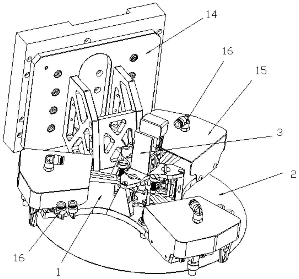
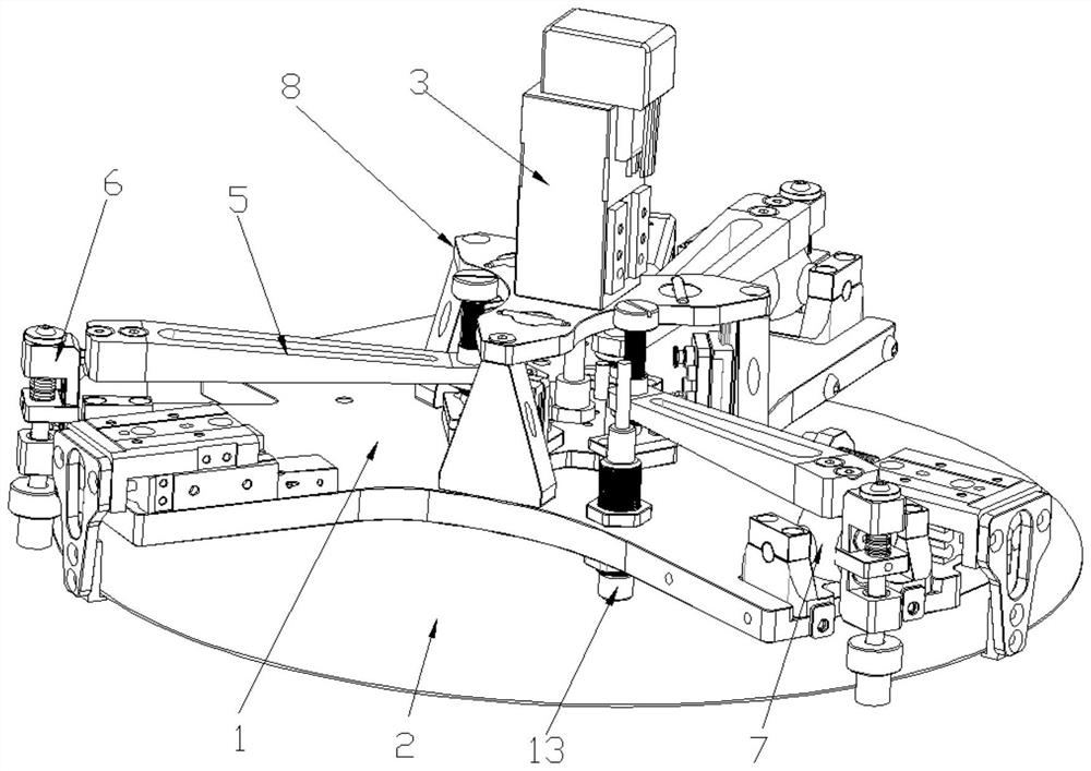
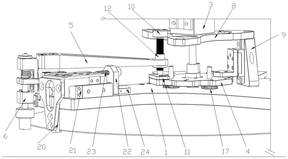
[0029] Such as Figure 1-6 As shown, a lever-driven wafer positioning and lifting mechanism includes a positioning device and a lifting device. Both the positioning device and the lifting device are installed on the bottom plate 1. The positioning device realizes the precise positioning of the wafer 2. Realize that the wafer 2 is picked up and put down.

[0030] The positioning device comprises a driving device 3, a center plate 4, a buffer device, and at least three groups of crowbars 5 and floating positioning fingers 6, and the buffer device is a plurality of springs 17 arranged between the base plate 1 and the center plate ...


PUM


Abstract

The invention discloses a lever-driven wafer positioning and supporting mechanism, which comprises a positioning device and a supporting device which are arranged on a bottom plate, and is characterized in that the positioning device comprises a driving device, a central plate, a buffer device, and at least three groups of pinch bars and floating positioning fingers which are uniformly arranged along the circumferential direction of the central plate; the buffer device is a spring arranged between the bottom plate and the center plate; the driving device presses the center plate downwards and enables the spring to be compressed, the wafer enters the inner side of the floating positioning fingers, then the driving device rotates, the spring releases stored energy to push the center plate to move upwards, the three pinch bars are lifted up at the same time, the three floating positioning fingers draw close to the center at the same time for centering and clamping, and synchronous centripetal of the wafer is achieved. The height and the position of the pinch bar are adjusted through the fine adjustment structure, and errors generated in part machining are made up; a floating positioning finger is adopted, and the wafer is close to a placement surface as far as possible during descending through stretching, so that deviation or damage caused by wafer placement is prevented; in addition, the buffer device prevents the wafer from being broken due to overlarge transmission rigidity.

Description

technical field [0001] The invention belongs to the technical field of wafer manufacturing, and in particular relates to a lever-driven wafer positioning and lifting mechanism. Background technique [0002] The wafer manufacturing process generally includes processes such as deoxidation purification, manufacturing ingots, wafer slicing, Wafer polishing, Wafer coating, photoresist coating, photolithography, ion injection, polishing, wafer slicing and testing. During the process, the wafer needs to be moved from the preparation station to the grinding table station for grinding. The wafer needs to be fixed on the grinding table in a precise position to facilitate the subsequent grinding work. In the wafer moving station In the process of positioning, a clamping tool is needed. In order to make the wafer accurately located in the center of the clamping tool, the wafer needs to be centered first. Because the size of the wafer itself has errors, it is placed on the preparation st...

Claims


Application Information

Patent Timeline
Patent Type & Authority Applications(China)
IPC IPC(8): B24B29/02B24B41/00B24B41/06B24B47/00
CPCB24B29/02B24B41/005B24B41/06B24B41/007B24B47/00B24B41/00
Inventor 许剑锋于世超张建国郑正鼎侍大为
Owner HUAZHONG UNIV OF SCI & TECH
Learn More