Method and device for calculating residual electric energy of electric energy storage equipment and power supply system

A technology of residual electric energy and calculation method, applied in the field of electric energy storage, can solve problems such as uncertain mapping relationship, limited calculation accuracy and efficiency, and inability to realize real-time calculation, and achieve high calculation timeliness

Pending Publication Date: 2022-05-10
APUTURE IMAGING IND CO LTD
View PDF0 Cites 0 Cited by
  • Summary
  • Abstract
  • Description
  • Claims
  • Application Information

AI Technical Summary

Problems solved by technology

However, the existing residual power calculation schemes generally only focus on establishing the mapping relationship between a fixed output voltage and residual power through experiments, so as to determine the residual power of the electric energy storage device through the detected output voltage by looking up the table. Electric energy, but this method requires pre-experimentation to obtain the mapping relationship, which cannot be calculated in real time, and because the mapping relationship between the output voltage of different types of electric energy storage devices and the remaining electric energy is uncertain, the existing remaining electric energy calculation The calculation accuracy and efficiency of the scheme are limited, and it is urgent to study a more accurate and efficient remaining power calculation scheme

Method used


Image

  • Method and device for calculating residual electric energy of electric energy storage equipment and power supply system
  • Method and device for calculating residual electric energy of electric energy storage equipment and power supply system
  • Method and device for calculating residual electric energy of electric energy storage equipment and power supply system

Examples


Embodiment 1

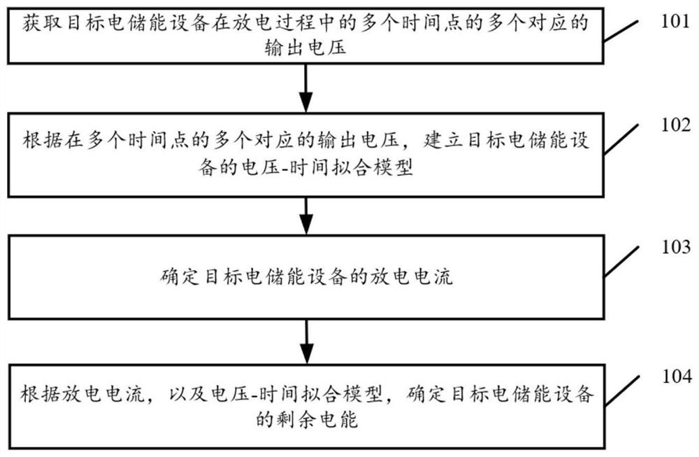
[0094] see figure 1 , figure 1 It is a schematic flowchart of a method for calculating the remaining electric energy of an electric energy storage device disclosed in an embodiment of the present invention. in, figure 1 The described method for calculating remaining electric energy of an electric energy storage device can be applied to a remaining electric energy calculating system / computing device / calculating server (wherein, the server includes a local server or a cloud server). Such as figure 1 As shown, the method for calculating the remaining electric energy of the electric energy storage device may include the following operations:

[0095] 101. Acquire multiple corresponding output voltages at multiple time points during a discharge process of a target electric energy storage device.

[0096] Optionally, the output voltage can be detected by a voltage detection device connected to the electric energy storage device.

[0097] Optionally, the electric energy storage ...

Embodiment 2

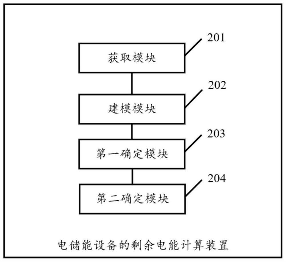
[0195] see figure 2 , figure 2 It is a structural schematic diagram of a remaining electric energy calculation device of an electric energy storage device disclosed in an embodiment of the present invention. in, figure 2 The described apparatus for calculating remaining electric energy of an electric energy storage device may be applied in a remaining electric energy calculating system / computing device / calculating server (wherein, the server includes a local server or a cloud server). Such as figure 2 As shown, the remaining electric energy calculation device of the electric energy storage device may include:

[0196] An acquisition module 201, configured to acquire multiple corresponding output voltages at multiple time points during the discharge process of the target electric energy storage device;

[0197] A modeling module 202, configured to establish a voltage-time fitting model of the target electric energy storage device according to multiple corresponding outp...

Embodiment 3

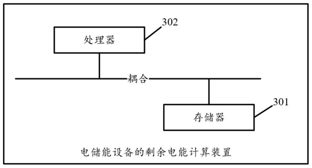
[0234] see image 3 , image 3 It is another remaining electric energy calculation device of an electric energy storage device disclosed in an embodiment of the present invention. image 3 The described apparatus for calculating remaining electric energy of an electric energy storage device may be applied in a remaining electric energy calculating system / computing device / calculating server (wherein, the server includes a local server or a cloud server). Such as image 3 As shown, the remaining electric energy calculation device of the electric energy storage device may include:

[0235] A memory 301 storing executable program codes;

[0236] a processor 302 coupled to the memory 301;

[0237] Wherein, the processor 302 invokes the executable program code stored in the memory 301 to execute some or all steps of the method for calculating the remaining electric energy of the electric energy storage device described in the first embodiment.


PUM


Abstract

The invention discloses a method and a device for calculating residual electric energy of electric energy storage equipment and a power supply system. The method comprises the following steps: acquiring a plurality of corresponding output voltages of target electric energy storage equipment at a plurality of time points in a discharging process; establishing a voltage-time fitting model of the target electric energy storage equipment according to the plurality of corresponding output voltages at the plurality of time points; determining the discharge current of the target electric energy storage equipment; and determining the residual electric energy of the target electric energy storage equipment according to the discharge current and the voltage-time fitting model. Therefore, the fitting model of the target electric energy storage equipment can be established based on the relation between the output voltage and the time acquired in the discharging process, so that the real-time calculation of the residual electric energy of the target electric energy storage equipment is realized, and a more accurate calculation effect and higher calculation timeliness are realized.

Description

technical field [0001] The invention relates to the technical field of electric energy storage, in particular to a method, device and power supply system for calculating remaining electric energy of electric energy storage equipment. Background technique [0002] The development of electric energy storage technology has made electric energy storage equipment such as lithium batteries and rechargeable batteries gradually become popular energy storage equipment and power supply equipment, and the calculation of the remaining electric energy parameters of electric energy storage equipment has gradually become a measure of the quality of electric energy storage equipment. important step in the situation. However, the existing residual power calculation schemes generally only focus on establishing the mapping relationship between a fixed output voltage and residual power through experiments, so as to determine the residual power of the electric energy storage device through the d...

Claims


Application Information

Patent Timeline
Patent Type & Authority Applications(China)
IPC IPC(8): G01R31/36
CPCG01R31/36
Inventor 林武龙
Owner APUTURE IMAGING IND CO LTD
Why Eureka
Try Eureka