Flaring mechanism and flaring device

A technology for clamping components and mounting platforms, which is used in electromechanical devices, manufacturing motor generators, electrical components, etc., can solve the problems of ensuring the straightness of flat wires and the accuracy of bending, and achieve the effect of improving straightness.

Active Publication Date: 2022-05-10
SHENZHEN JINMINJIANG RIVER MECHANICAL & ELECTRICAL EQUIP
View PDF3 Cites 1 Cited by
  • Summary
  • Abstract
  • Description
  • Claims
  • Application Information

AI Technical Summary

Problems solved by technology

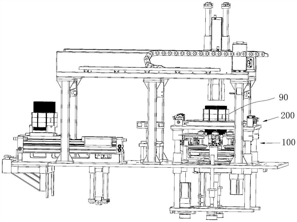
[0005] The purpose of the present invention is to provide a flaring mechanism and a flaring device, aiming to solve the technical problem of ensuring the straightness and bending accuracy of the flat wire by the existing flaring device method

Method used


Image

  • Flaring mechanism and flaring device
  • Flaring mechanism and flaring device
  • Flaring mechanism and flaring device

Examples


Embodiment Construction

[0030] Embodiments of the present invention are described in detail below, examples of which are shown in the drawings, wherein the same or similar reference numerals designate the same or similar elements or elements having the same or similar functions throughout. The embodiments described below by referring to the figures are exemplary and are intended to explain the present invention and should not be construed as limiting the present invention.

[0031] In describing the present invention, it should be understood that the terms "length", "width", "upper", "lower", "front", "rear", "left", "right", "vertical", The orientations or positional relationships indicated by "horizontal", "top", "bottom", "inner", "outer", etc. are based on the orientation or positional relationships shown in the drawings, and are only for the convenience of describing the present invention and simplifying the description, and It is not to indicate or imply that the device or element referred to m...


PUM


Abstract

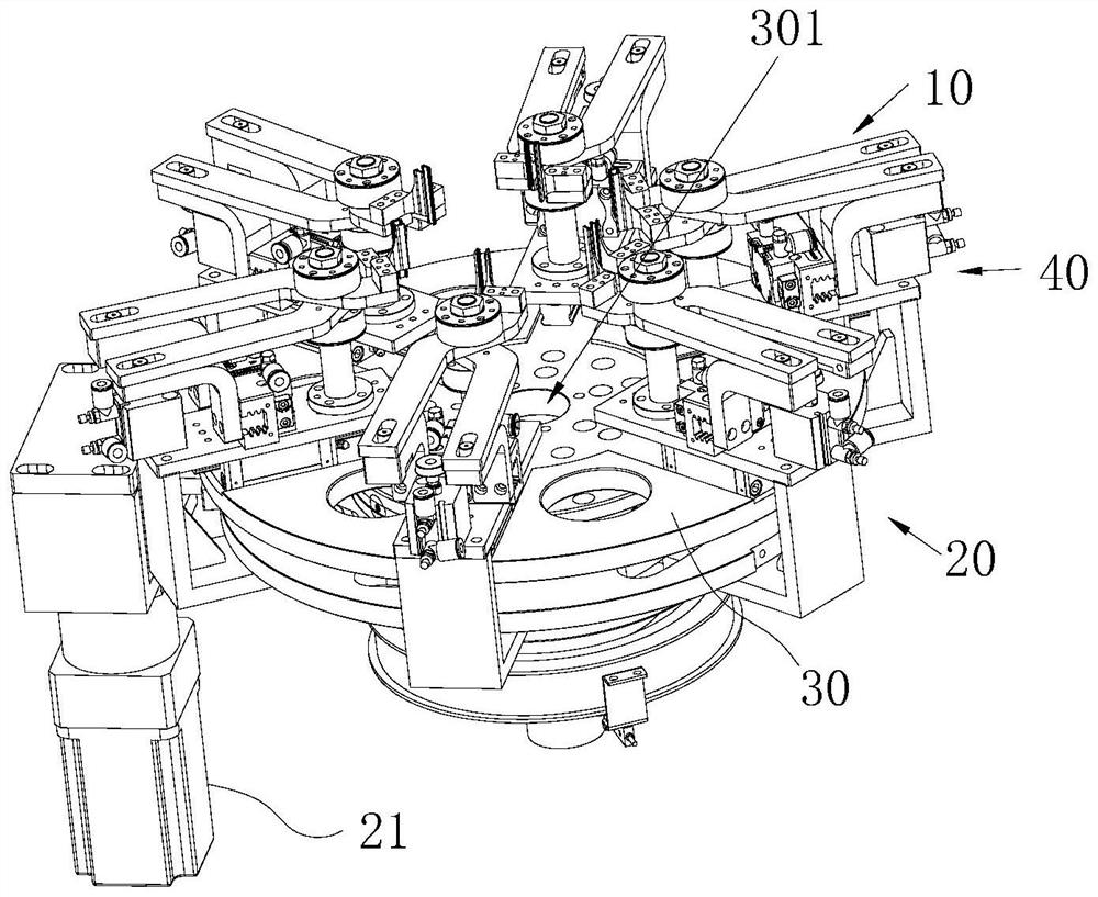
The invention provides a flaring mechanism and a flaring device.The flaring mechanism comprises a clamping assembly and a moving assembly, the clamping assembly comprises a clamping component and a clamping driving part, the clamping component comprises a first clamping piece and a second clamping piece, and the clamping driving part can drive the first clamping piece and the second clamping piece to get close to each other or get away from each other; the clamping component is switched between an opening state in which the distance between the first clamping piece and the second clamping piece is larger than a preset value and a clamping state in which the first clamping piece and the second clamping piece jointly clamp the flat wire, and the preset value is larger than the thickness of the flat wire; the moving assembly comprises a moving driving piece, and the moving driving piece can drive the clamping assembly to move in the flaring direction when the clamping component is in the clamping state. According to the flaring mechanism, clamping and flaring of the flat wire are achieved through the clamping component, meanwhile, the moving direction of the flat wire is corrected, the straightness of the flat wire is improved, and therefore it is guaranteed that the head twisting procedure in the later period is conducted smoothly.

Description

technical field [0001] The invention belongs to the technical field of motor assembly equipment, and in particular relates to a flaring mechanism and a flaring device. Background technique [0002] As the country vigorously promotes energy conservation and environmental protection, new energy vehicles have developed rapidly. As the core component of new energy vehicles, the drive motor plays a vital role. Among them, during the assembly process of the driving motor, it is necessary to expand the flat wires of each layer of the stator first, and then perform layered twisting on the expanded flat wires. [0003] As the new energy vehicle drive motor stator requires more and more layers of flat wires, the number of mold slots corresponding to the stator flat wires also doubles when performing layered twisting, and as long as one flat wire is bent and deformed, or When it is skewed during the flaring process, it cannot be inserted into the notch, which leads to the failure of ...

Claims


Application Information

Patent Timeline
Patent Type & Authority Applications(China)
IPC IPC(8): H02K15/00
CPCH02K15/0031
Inventor 郑湘宏
Owner SHENZHEN JINMINJIANG RIVER MECHANICAL & ELECTRICAL EQUIP
Why Eureka
Try Eureka