Dish washing machine drying device

A technology of drying device and dishwasher, applied in the field of kitchen furniture, can solve the problems of slow drying speed of tableware, reduced impact force of nozzles, increased external resistance of rotating nozzles, etc., to achieve the effect of accelerating drying speed

Pending Publication Date: 2022-05-13
陈行
View PDF9 Cites 0 Cited by
  • Summary
  • Abstract
  • Description
  • Claims
  • Application Information

AI Technical Summary

Problems solved by technology

[0002] The dishwasher is a device for automatically cleaning tableware such as tableware. Its working principle is to use high-temperature and high-pressure water with detergent to rinse, decontaminate and clean the tableware in the dishwasher. The existing dishwasher Almost all of them can meet the requirements of tableware cleanliness, but there are still deficiencies in tableware cleaning and drying.
[0003] When the existing dishwashers use high-temperature and high-pressure water for impact cleaning, a large amount of water vapor will be generated, and this water vapor will not be sucked away by the exhaust fan until the subsequent drying process, which leads to dishwashing. The inside of the machine will form a high-pressure environment during cleaning, which will increase the external resistance of the rotating nozzle when it sprays high-temperature and high-pressure water, resulting in a decrease in the impact force of the nozzle, which is not conducive to completing impact cleaning. At the same time, in the drying process, the exhaust fan will The water vapor is drawn away, which will cause a negative pressure state in the dishwasher, which will reduce the temperature in the dishwasher and slow down the drying speed of the dishes

Method used


Image

  • Dish washing machine drying device
  • Dish washing machine drying device
  • Dish washing machine drying device

Examples


Embodiment Construction

[0026] The following will be combined with the accompanying drawings in the embodiments of the present invention, the technical solution in the embodiments of the present invention will be described clearly and completely, it is clear that the embodiments described are only a part of the embodiment of the present invention, not all embodiments. Based on embodiments in the present invention, all other embodiments obtained by those of ordinary skill in the art without making creative work, are within the scope of protection of the present invention.

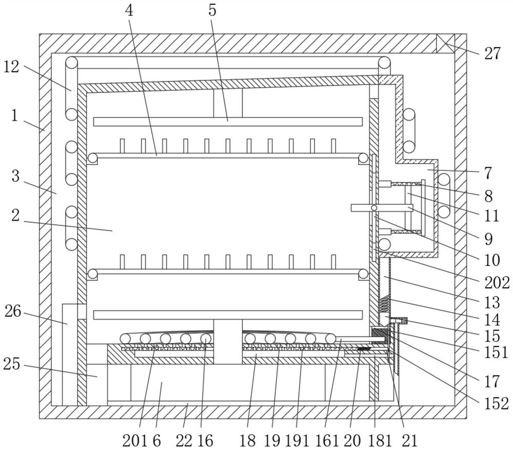
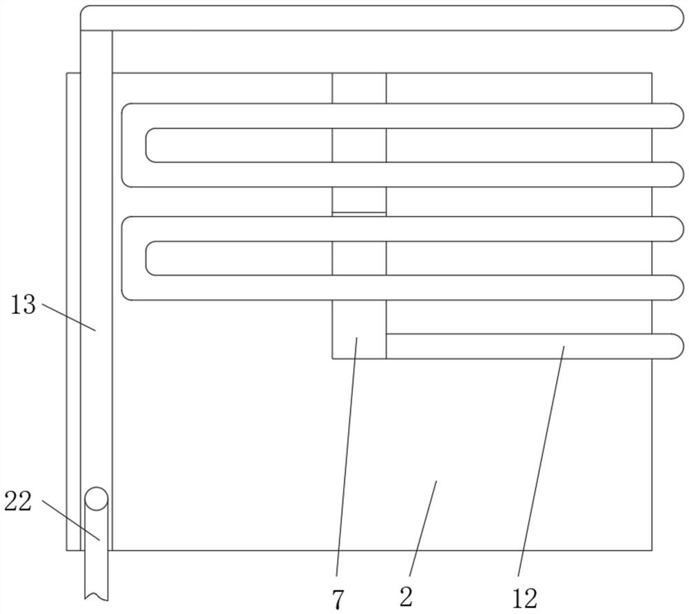
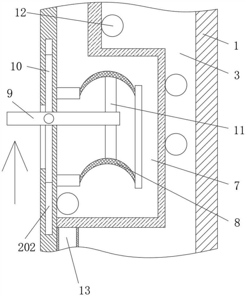
[0027] See Figure 1 、 Figure 4-Figure 5 、 Figure 7 , a dishwasher drying device, comprising a rack 1, a cleaning box 2 in the rack 1, a powertrain at the bottom end of the cleaning box 2 6, a bracket 4 in the cleaning box 2, a rotating sprinkler at the bottom and top of the cleaning box 2, a drain pipe 25 and an inlet pipe 26 at the bottom of the cleaning box 25, a powertrain 6 comprising the main drive device of the dishwasher, su...


PUM


Abstract

The invention relates to the technical field of kitchen furniture, and discloses a dish-washing machine drying device which comprises a rack, a cleaning box in the rack, a power assembly at the bottom end of the cleaning box, a support in the cleaning box, rotary nozzles at the bottom end and the top end of an inner cavity of the cleaning box, and a drainage pipe and a water inlet pipe at the bottom of the cleaning box. Through the designed suction pipe, the driving rod, the ejector rod and the elastic rubber layer I, when rotating nozzles conduct rotating impact cleaning on bowls and chopsticks, the upper rotating nozzle and the lower rotating nozzle can intermittently impact the driving rod, so that the driving rod moves up and down, the ejector rod is driven to extrude and pull the elastic rubber layer I, the space in the suction pipe is intermittently changed, and the cleaning effect is improved. According to the cleaning device, the suction pipe is arranged, so that the suction pipe sucks away high-temperature and high-pressure water vapor in the cleaning box, the air pressure in the cleaning box is reduced, the spraying resistance borne by a spray head is reduced, meanwhile, the condensation pipe and the hollow cavity are designed, the high-temperature and high-pressure water vapor circulates in the condensation pipe and releases heat, air in the hollow cavity is heated, and high-pressure expansion gas is formed.

Description

Technical field [0001] The present invention relates to the technical field of kitchen furniture, specifically a dishwasher drying device. Background [0002] Dishwasher is automatic cleaning of dishes and chopsticks and other tableware equipment, its working principle is mainly the use of high temperature and high pressure water with detergent to wash and clean the tableware in the dishwasher, the existing dishwasher can almost meet the requirements of tableware cleanliness, but in the tableware cleaning and drying link, there are still deficiencies. [0003] The existing dishwasher will produce a large amount of water vapor when using high temperature and high pressure water for impact cleaning, and this water vapor will be pumped away under the action of the exhaust fan until the subsequent drying link, which will lead to the formation of a high-pressure environment inside the dishwasher during cleaning, so that the external resistance of the rotating nozzle when spraying out...

Claims


Application Information

Patent Timeline
Patent Type & Authority Applications(China)
IPC IPC(8): A47L15/22A47L15/42A47L15/48
CPCA47L15/22A47L15/4285A47L15/483A47L15/42
Inventor 陈行
Owner 陈行
Why Eureka
Try Eureka