

Lamp for vehicles
A technology for lamps and vehicles, which is applied to vehicle components, vehicle lighting systems, discharge lamps, etc., can solve the problems of limited freedom, cost, and poor brazing, and achieve the effect of increasing freedom.
- Summary
- Abstract
- Description
- Claims
- Application Information
AI Technical Summary
Problems solved by technology
Method used
Image

Examples
Embodiment Construction
[0017] Next, embodiments of the vehicle lamp according to the present invention will be described with reference to the drawings.
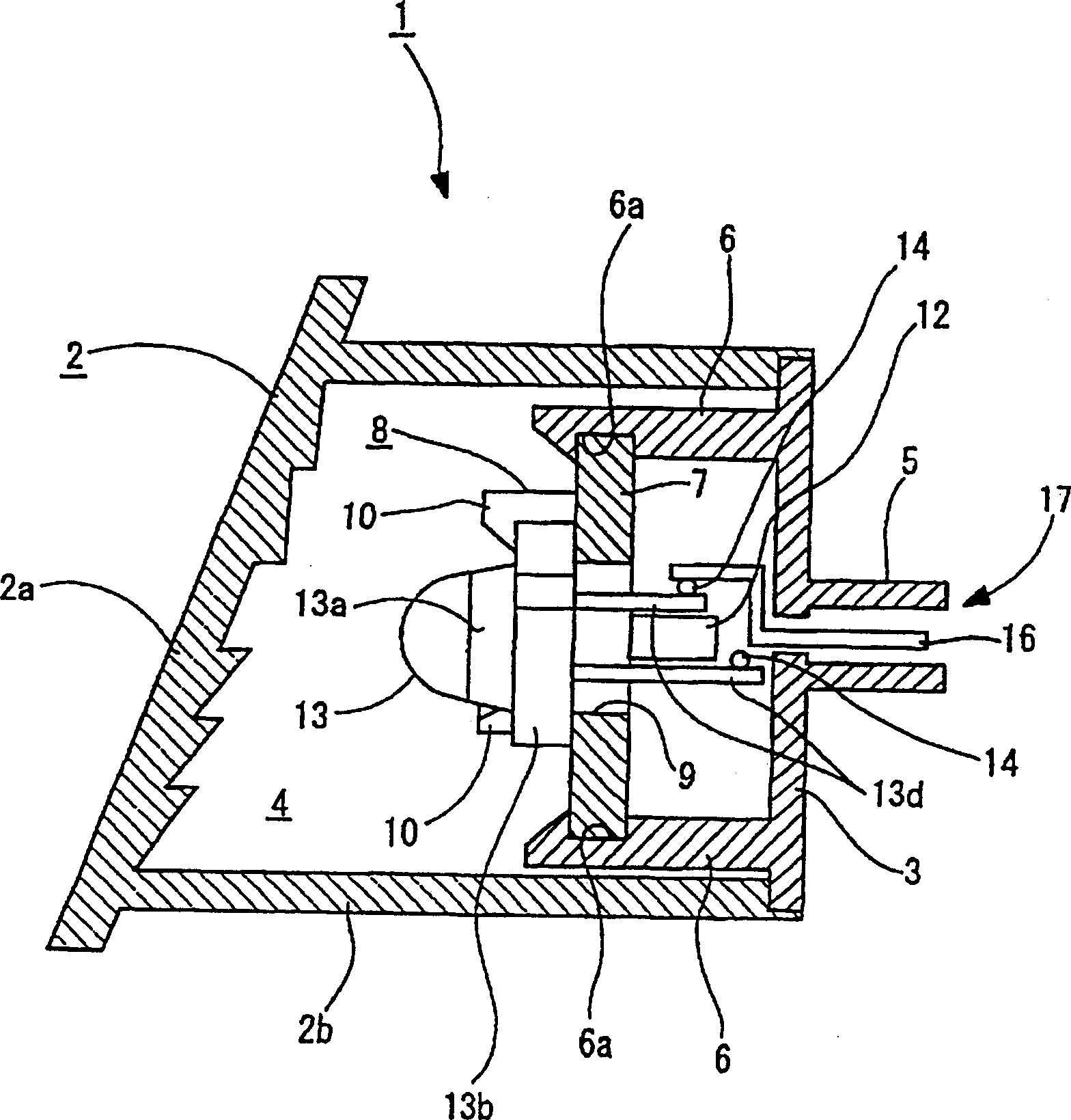
[0018] The illustrated vehicle lamp 1 is suitable for an overhead parking light, that is, a parking light arranged inside a rear windshield of a car.
[0019] The rear end of the lens 2 of the vehicle lamp 1 is covered by the lamp body 3 to form a lamp chamber 4 composed of the lens 2 and the lamp body 3 . A front portion 2a long in the left-right direction of the lens 2 and a peripheral wall portion 2b protruding rearward from the peripheral edge of the front portion 2a are integrally formed of a red colored transparent synthetic resin. At the rear end of the peripheral wall portion 2b of such a lens 2, a lamp chamber 4 to which a substantially plate-shaped lamp body 3 can be attached is formed. A cylindrical portion 5 protruding rearward is integrally formed on the lamp body 3 .
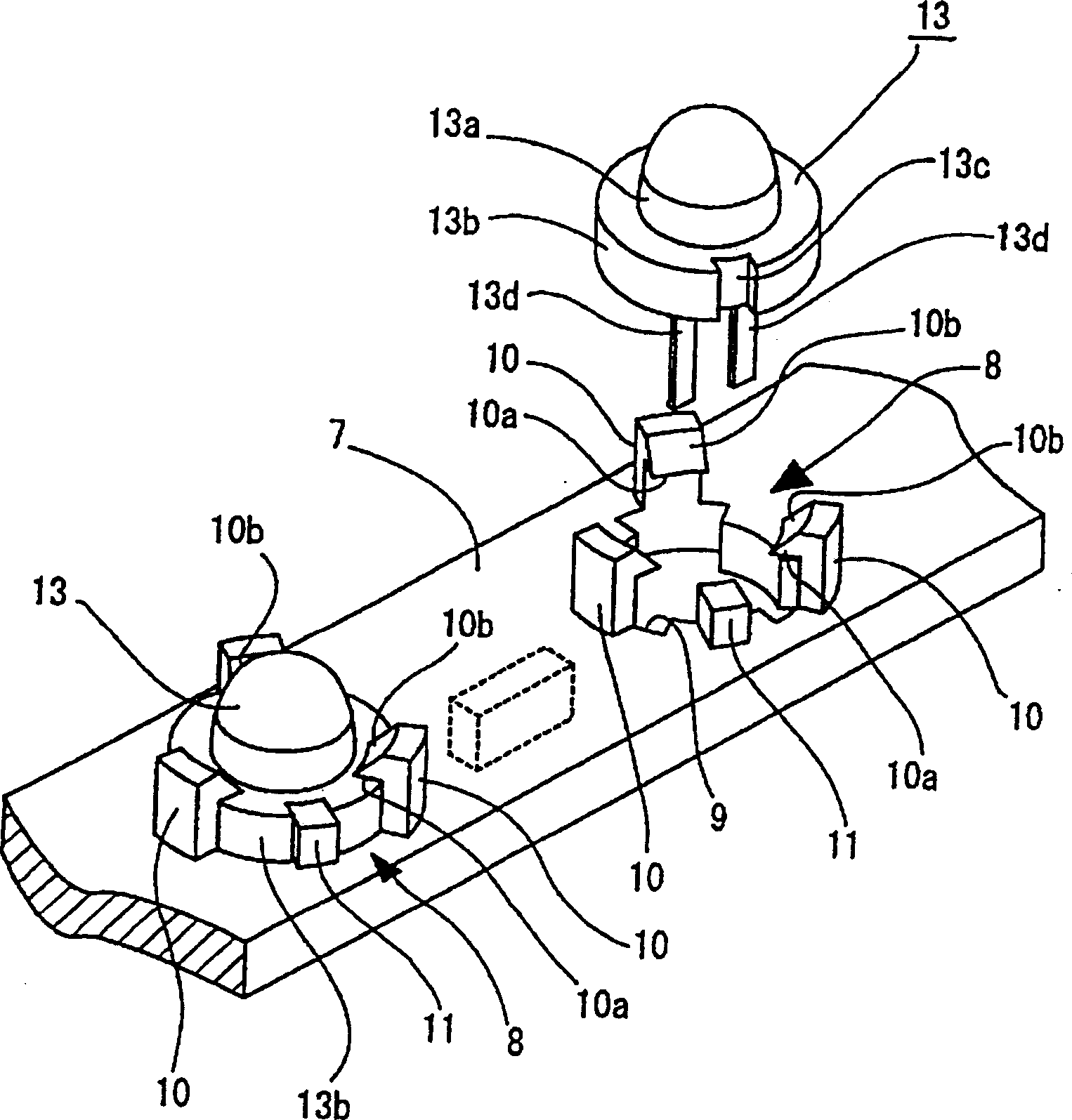
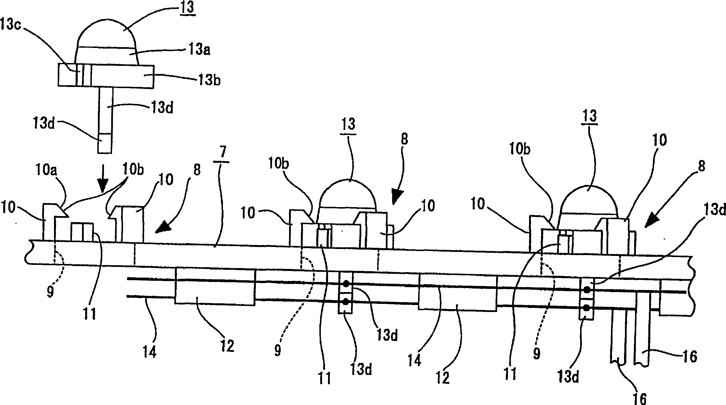
[0020] Support walls 6 , 6 protrude forward from upper and lowe...
PUM
 Abstract
Description
Claims
Application Information