Comprehensive crusher capable of screening finished products according to material crushing state
A material crushing and crushing machine technology, which is applied in the fields of filtering, solid separation, grain processing, etc., can solve problems such as damage to the rolling edge of the knife roll, shorten the service life of the device, and affect the crushing effect of the knife roll, so as to avoid clogging, fast and efficient broken effect
- Summary
- Abstract
- Description
- Claims
- Application Information
AI Technical Summary
Problems solved by technology
Method used
Image
Examples
Embodiment 1
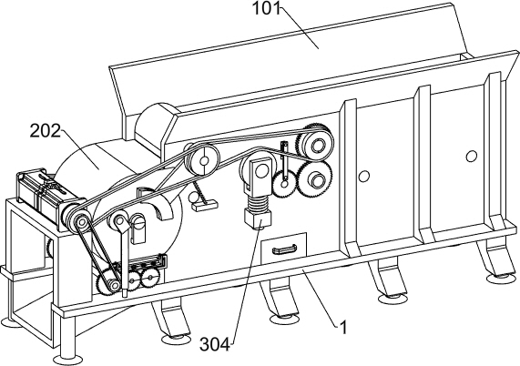
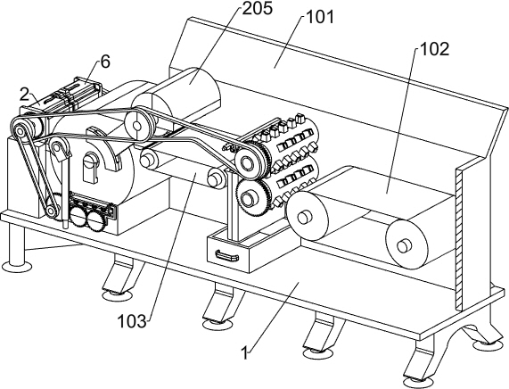
[0034] A kind of integrated crusher for sifting finished products according to the crushing state of the material, such as Figure 1 and Figure 2Shown, comprising a base 1, a first protective shell 101, a first conveying platform 102, a second conveying platform 103, a feeding mechanism, a rolling mechanism, a hammering mechanism and a crushing mechanism, the upper right end of the base 1 is fixed with a first protective shell 101, the left part of the first protective shell 101 is opened with two curved grooves, the first protective shell 101 has a first conveying platform 102 and a second conveying platform 103, the first conveying platform 102 is located on the right side of the second conveying platform 103, The upper end surface of the first conveying platform 102 is parallel to the upper end surface of the second conveying platform 103, the left part of the first protective shell 101 is provided with a feeding mechanism, the feeding mechanism is used to transport the materi...
Embodiment 2
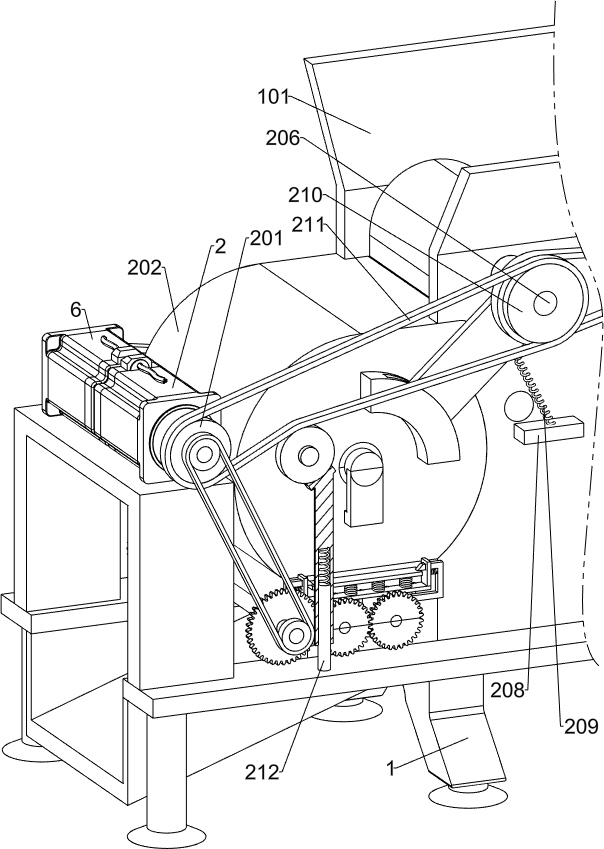
[0037] On the basis of Example 1, e.g., Figure 3 、 Figure 4 and Figure 11As shown, the feeding mechanism comprises a first drive motor 2, a first chainring 201, a second protective case 202, an arc fixing block 203, a turning plate 204, a third protective shell 205, a first rotating shaft 206, a roller 207, a rectangular fixing block 208, a first pulley 209, a second sprocket 210, a first chain 211 and a first compression assembly 212, the upper left end of the base 1 is fixed by a connecting frame with a first drive motor 2, the output shaft of the first drive motor 201 is fixed on the output shaft of the first drive motor 201, The left end of the first protective shell 101 is fixed with a second protective shell 202, the upper right end of the second protective shell 202 is provided with a rectangular opening, the lower end of the second protective shell 202 is provided with a rectangular through hole, the lower end face of the rectangular mouth of the second protective shell...
Embodiment 3
[0048] On the basis of Example 2, e.g., Figure 12-Figure 14Shown, further comprising an anti-jamming mechanism, the second protective shell 202 is provided with an anti-plugging mechanism, the anti-blocking mechanism includes an outlet 7, a fourth rotating shaft 701, a third spur gear 702, a fourth spur gear 703, a cam 704, a fixed mesh 705, a sliding screen 706, a first fixing plate 707, a second spring 708, a second fixing plate 709, a special-shaped sliding rod 710 and a second tensile spring 711, the lower end of the second protective shell 202 is fixed with an outlet 7, Outlet 7 is facing the rectangular through hole of the second protective shell 202, the left end of the outlet 7 is provided with a fourth rotation shaft 701 through the connection block rotation, the front end of the fourth rotation axis 701 is provided with a sprocket, the front end of the first drive motor 2 is also provided with a sprocket, the first drive motor 2 is also provided with a sprocket between...
PUM
 Abstract
Description
Claims
Application Information
 - R&D
- Intellectual Property
- Life Sciences
- Materials
- Tech Scout
- Unparalleled Data Quality
- Higher Quality Content
- 60% Fewer Hallucinations
Browse by: Latest US Patents, China's latest patents, Technical Efficacy Thesaurus, Application Domain, Technology Topic, Popular Technical Reports.
© 2025 PatSnap. All rights reserved.Legal|Privacy policy|Modern Slavery Act Transparency Statement|Sitemap|About US| Contact US: help@patsnap.com


