Manipulator-based motor quick-changing device and changing method thereof
A technology of manipulators and reducers, which is applied in the direction of manipulators, manufacturing tools, chucks, etc., can solve the problem that the installation method cannot meet the needs of remote quick change of motors, and achieve the effect of ensuring safety
- Summary
- Abstract
- Description
- Claims
- Application Information
AI Technical Summary
Problems solved by technology
Method used
Image
Examples
Embodiment 1
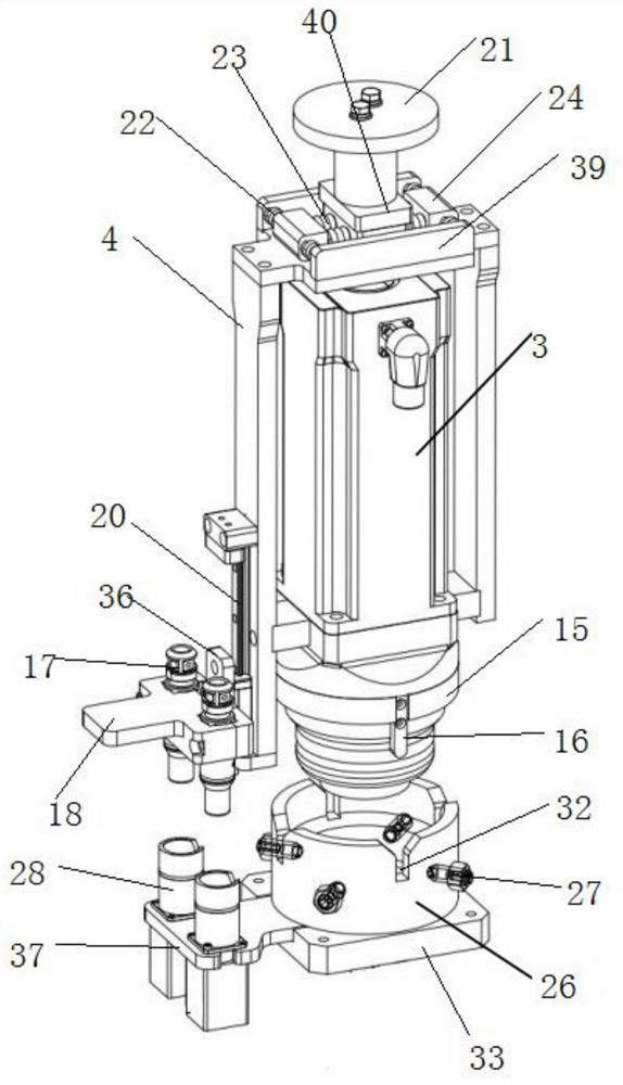
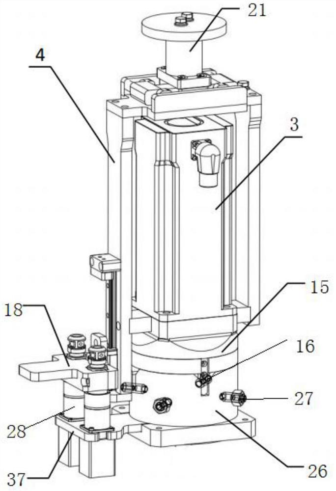
[0038] A motor quick change device, such as figure 1 with figure 2 As shown, the quick-change module, the fixed module, and the guide assembly that assists the docking of the quick-change module and the fixed module;
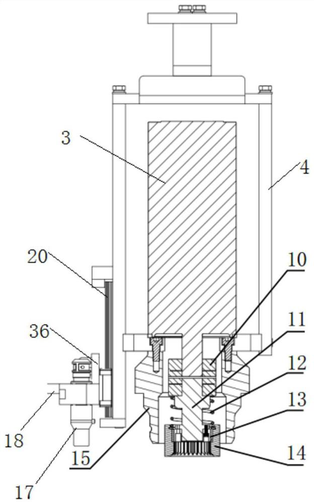
[0039] Wherein, the quick change module such as image 3 As shown, it includes a frame 4 for installing the motor 3, a flexible clamping assembly fixedly installed above the frame 4, a mechanical docking assembly connected to the output shaft of the motor 3, and a frame mounted on the side of the frame 4. Aviation plug assembly;
[0040] The mechanical docking assembly includes a gear shaft 11 connected to the output shaft of the motor 3 through a coupling 10, an upper external gear 13 mounted on the lower end of the gear shaft 11, and a mounting assembly floating up and down on the upper gear shaft. The inner ring gear 14 outside the outer gear 14 and meshed with the upper outer gear 13; the installation assembly includes a compression spring 12 sleeved on ...
Embodiment 2
[0049] This embodiment introduces its guide assembly on the basis of Embodiment 1.
[0050] The guide assembly includes a guide sleeve 15 coaxially arranged with the output shaft of the motor 3 and a positioning sleeve 26 arranged coaxially with the input shaft 30 of the reducer. The upper end of the positioning sleeve 26 is open, and the guide sleeve 15 is inserted downward into the positioning sleeve 26 to achieve axial positioning; the outer wall of the guide sleeve 15 is provided with a positioning pin 16, and the positioning sleeve 26 is provided with a positioning groove 32 for the insertion of the positioning pin 16, so that The positioning pin 16 is inserted into the positioning slot 32 to achieve circumferential positioning. The mechanical docking assembly is located in the inner cavity of the guide sleeve 15 , and the lower edges of the upper external gear 13 and the inner ring gear 14 are lower than the lower edges of the guide sleeve 15 .
[0051] Preferably, both...
Embodiment 3
[0055] This embodiment introduces its flexible clamping component on the basis of Embodiment 1.
[0056] A flexible clamping assembly for clamping by the manipulator is fixedly installed above the frame 4 . The flexible clamping assembly includes two fixed plates 39 relatively fixed on the frame, two sets of Y-direction flexible connectors located between the two fixed plates 39, and two sets of Y-directed flexible connectors located between the two sets of Y-directed flexible connectors. The X-direction flexible connector and the clamping block 21 for the manipulator to clamp, under the connection action of the X-direction flexible connector and the Y-direction flexible connector, the clamping block 21 and the frame 4 constitute flexible connection;
[0057] Each group of Y-direction flexible connectors includes a spring limiting block 24 and two first springs 22. Internal elastic connection;
[0058] The X-direction flexible connector includes a flexible base 40 and two s...
PUM
 Abstract
Description
Claims
Application Information
 - R&D
- Intellectual Property
- Life Sciences
- Materials
- Tech Scout
- Unparalleled Data Quality
- Higher Quality Content
- 60% Fewer Hallucinations
Browse by: Latest US Patents, China's latest patents, Technical Efficacy Thesaurus, Application Domain, Technology Topic, Popular Technical Reports.
© 2025 PatSnap. All rights reserved.Legal|Privacy policy|Modern Slavery Act Transparency Statement|Sitemap|About US| Contact US: help@patsnap.com


