A new type of hydraulic control system for transfer loader

A technology of hydraulic control system and transfer machine, applied in mechanical equipment, fluid pressure actuating device, servo motor, etc., can solve the problems of high investment cost, high cost of spare parts, high energy consumption in production and operation, etc. Low consumption, low cost of spare parts in the later period, and the effect of avoiding equipment damage

Active Publication Date: 2017-03-22
CHINA NAT HEAVY MACHINERY RES INSTCO
View PDF7 Cites 0 Cited by
  • Summary
  • Abstract
  • Description
  • Claims
  • Application Information

AI Technical Summary

Problems solved by technology

This known technical solution has the problems of high investment cost in the early stage, high energy consumption in production and operation, and high cost of spare parts in the later stage.

Method used


Image

  • A new type of hydraulic control system for transfer loader

Examples


Embodiment Construction

[0025] The present invention will be described in detail below in conjunction with the accompanying drawings and embodiments.

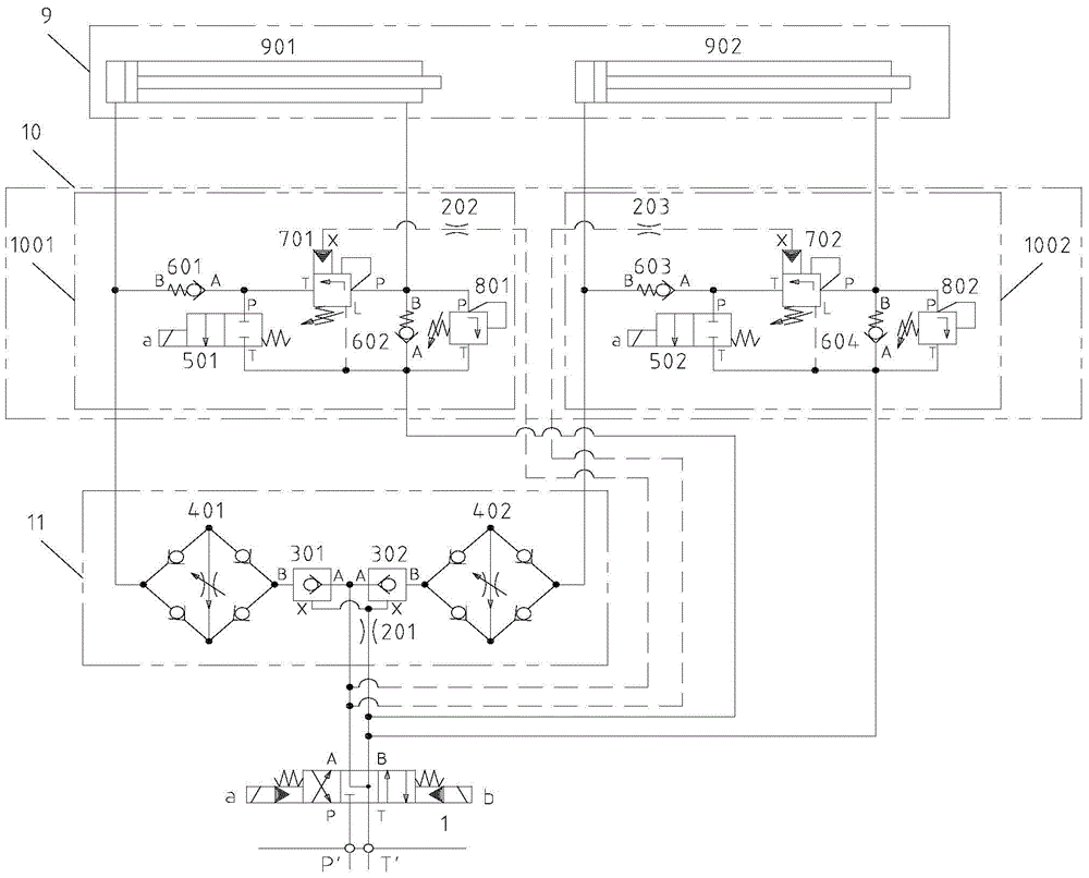
[0026] see figure 1 , a new hydraulic control system for a transfer machine, including an electro-hydraulic reversing valve 1, a speed adjustment and position locking unit 11, an acceleration control unit 10, and a hydraulic cylinder unit 9; wherein,

[0027] The plug cavity and the rod cavity of the hydraulic cylinder unit 9 are respectively connected to the electro-hydraulic reversing valve 1 through the speed-increasing control unit 10, the speed adjustment and position locking unit 11, and the electro-hydraulic reversing valve 1 is connected to the main pressure pipeline and the main circuit. The oil pipeline is connected.

[0028] The hydraulic cylinder unit 9 is composed of a first hydraulic cylinder 901 and a second hydraulic cylinder 902 .

[0029] The speed-up control unit 10 is composed of a first speed-up control unit 1001 and a second sp...


PUM


Abstract

The invention provides a novel hydraulic control system of a transfer-machine and relates to the field of continuous steel casting in the metallurgical industries. The novel hydraulic control system comprises an electro-hydraulic directional control valve, a speed regulating and position locking unit, a speed increase control unit and a hydraulic cylinder unit. A piston cavity and a rod cavity of the hydraulic cylinder unit are sequentially connected with the electro-hydraulic directional control valve through the speed increase control unit and the speed regulating and position locking unit respectively, and the electro-hydraulic directional control valve is connected with a main pressure pipe and a main oil return pipe. According to the novel hydraulic control system, on the premise that increase of the power of a hydraulic pump station and increase of the drift diameter of a hydraulic component are not needed, the speed of a hydraulic cylinder can be greatly improved, and the requirement for quick motion of the transfer-machine is completely met; particularly when multiple hydraulic cylinders act at the same time, the investment and construction cost saving effect is more obvious; meanwhile, automatic switching between the high speed and the low speed of the hydraulic cylinder can be achieved according to the process control requirement, impact generated when equipment is started and stopped is prevented, and the equipment is prevented from being damaged.

Description

technical field [0001] The invention relates to a hydraulic control system of a transfer machine in the field of continuous steel casting in the metallurgical industry. Background technique [0002] At present, in order to improve the production operation rate of continuous casting machines at home and abroad, continuous casting machines with multiple streams are usually used in parallel production. At the end of the slab discharge area of ​​the continuous casting machine, a slab transfer device is used to merge the slabs with multiple streams and send them to the subsequent production line. As a slab transfer device with simple structure, high operating efficiency and low failure rate, the transfer machine is widely used in slab continuous casting machines. [0003] With the improvement of the production rate of continuous casting machines, the high-speed slab continuous casting machines require the transfer machine to have higher operating efficiency, that is, the hydraul...

Claims


Application Information

Patent Timeline
Patent Type & Authority Patents(China)
IPC IPC(8): F15B11/04F15B11/16
Inventor 丘铭军郭星良艾春璇
Owner CHINA NAT HEAVY MACHINERY RES INSTCO
Why Eureka
Try Eureka