Split-type reverse heat exchanger

A heat exchanger, split-flow technology, applied in the field of split-flow reverse heat exchangers, can solve the problems of wasting boiler rooms, environmental pollution, shortening the service life of boilers, etc., to reduce boiler damage, easy to use, and reduce fuel consumption. Effect

Inactive Publication Date: 2012-07-11
崔光辉
View PDF3 Cites 0 Cited by
  • Summary
  • Abstract
  • Description
  • Claims
  • Application Information

AI Technical Summary

Problems solved by technology

The boiler is the most common heating equipment in the city. Its main function is to provide heat for the user's heating equipment. The existing boilers all use a single combustion chamber to complete the heat exchange process. There is some waste, and the boiler room needs to be higher. After heat exchange, the low-temperature heat transfer medium directly passes through the heating pipe network loop into the boiler for heating and circulation. After reaching a certain temperature, it is supplied to each user through the pipe network. However, most of the existing boilers are Coal-fired boilers, so the method of direct heating by low-temperature heat transfer medium not only consumes a lot of coal, but also produces a large amount of boiler exhaust gas. These exhaust gases contain high concentrations of dust and the temperature is generally as high as 250 ° C. Direct discharge into the atmosphere will cause serious environmental pollution. ; In addition, the greater the temperature difference between the cold heat transfer medium and the boiler, the shorter the service life of the boiler

Method used


Image

  • Split-type reverse heat exchanger
  • Split-type reverse heat exchanger

Examples


Embodiment Construction

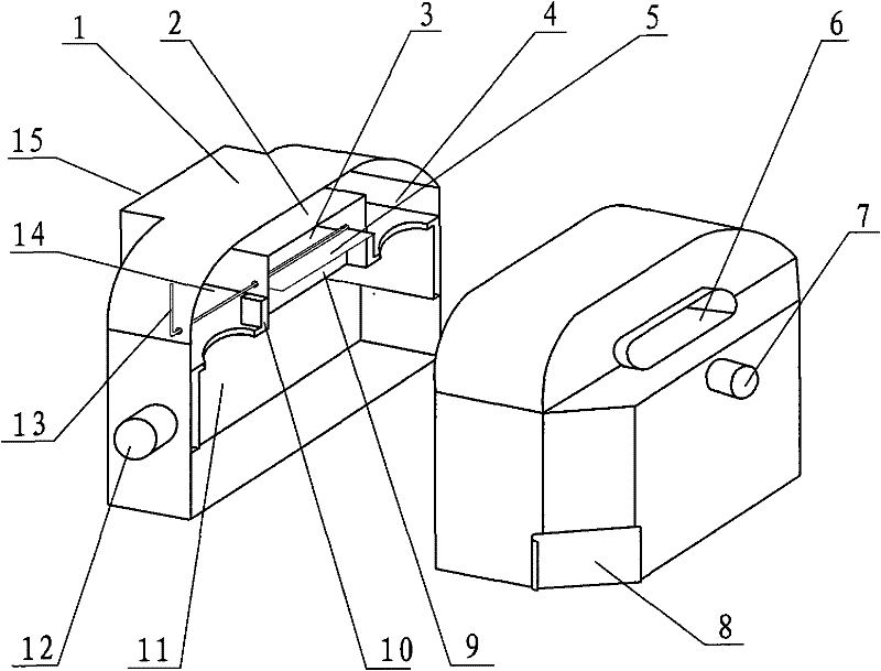
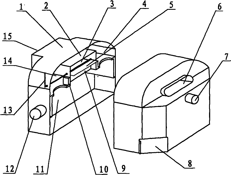
[0018] Such as figure 1 As shown, the main structure of the present invention includes a housing 1 with a smoke inlet 6 and a smoke outlet 15, and a three-way smoke pipe consisting of a straight-through smoke passage 3 and a retrograde smoke passage 9 is arranged on the upper side of the inside of the housing 1. The straight flue gas passage connects the flue gas inlet 6 and the flue gas outlet 15, the retrograde flue gas passage 9 is arranged below the combustion layer, and a controllable flue gas The flip baffle 5 of the flow direction is connected to the control handle 13; the water inlet 12 is arranged at the lower part of the side wall of the casing, and the water outlet 7 is arranged at the upper part of the side wall of the casing 1; 1 The body is provided with a stove-type circulating heat exchange jacket 10 which is connected to the water outlet 7 and the water inlet 12 and has a flue gas return port 4. The space of the shell 1 on the upper part of the circulating he...


PUM


Abstract

The invention relates to a split-type reverse heat exchanger which comprises a shell with a flue gas inlet and a flue gas outlet. The split-type reverse heat exchanger is technically characterized in that a tee-joint flue gas channel comprising a straight flue gas channel and a reverse flue gas channel is arranged at the inner upper side of the shell, the straight flue gas channel is communicatedwith flue gas inlet and the flue gas outlet, a turnover baffle capable of controlling the flowing direction of flue gas is arranged at the joint of the straight flue gas channel and the reverse flue gas channel, a heat-conducting medium inlet is arranged at the lower part of the side wall of the shell, a heat-conducting medium outlet is arranged at the upper part of the side wall of the shell, a circulating heat exchanging jacket which is communicated with the heat-conducting medium outlet and the heat-conducting medium inlet and provided with a flue gas pickup opening is arranged in the shell around the reverse flue gas channel, a shell space at the upper part of the circulating heat exchanging jacket is a flue gas uprise chamber, a shell space at the lower part, which is communicated with the reverse flue gas channel, is a flue gas dispersion chamber, and a backflow air vent is also arranged in the flue gas uprise chamber. The invention has high efficiency, energy saving, prolonged boiler service life, environmental protection, safety, reliability, low manufacture cost and convenient use.

Description

technical field [0001] The invention belongs to the technical field of heating and energy-saving equipment, and specifically relates to a boiler tail gas that can recoil downwards below the combustion layer and form a reverse direction with the flow direction of the cold heat-conducting medium in the loop in the heating pipe network, perform primary heating and then supply the boiler for secondary use Heated split-flow reverse heat exchanger. Background technique [0002] As we all know, with the rapid growth of world population and economy, energy consumption increases sharply. Today, with increasingly severe environmental pollution and increasingly endangered living environment, people's desire to be green, protect the environment, and save energy is also becoming increasingly strong. The boiler is the most common heating equipment in the city. Its main function is to provide heat for the user's heating equipment. The existing boilers all use a single combustion chamber t...

Claims


Application Information

Patent Timeline
Patent Type & Authority Patents(China)
IPC IPC(8): F24H9/00
Inventor 崔光辉
Owner 崔光辉
Why Eureka
Try Eureka