Manipulator flexible clamping structure and application of manipulator flexible clamping structure in quick change device
A technology of flexible clamping and manipulators, applied in the direction of manipulators, chucks, manufacturing tools, etc., can solve problems such as workpiece damage, achieve the effects of reducing eccentric load force, avoiding workpiece damage, and meeting action requirements
- Summary
- Abstract
- Description
- Claims
- Application Information
AI Technical Summary
Problems solved by technology
Method used
Image
Examples
Embodiment 1
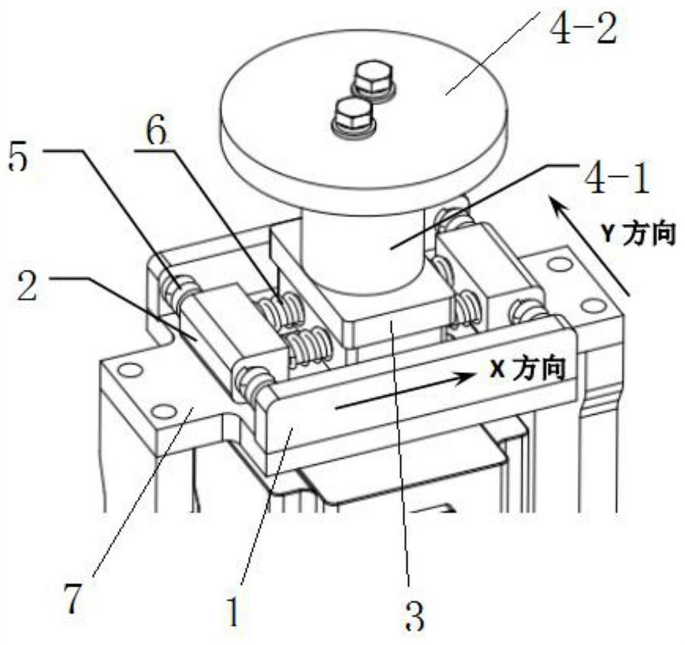
[0029] A flexible clamping structure of a manipulator, such as figure 1 As shown, it includes two fixed plates 1 relatively fixed on the frame, two sets of Y-direction flexible connectors between the two fixed plates 1, and X-direction flexible connectors between the two groups of Y-direction flexible connectors. The flexible connection piece and the operation block 4 clamped by the manipulator, under the connection action of the X-direction flexible connection piece and the Y-direction flexible connection piece, the operation block 4 and the frame form a flexible connection.
[0030] Each group of Y-direction flexible connectors includes a spring limiting block 2 and two first springs 5, and the two ends of the spring limiting block 2 are respectively connected to the ends of the fixing plate 1 by a first spring 5. Internal elastic connection.
[0031] The X-direction flexible connector includes a flexible base 3 and two second springs 6, and the opposite sides of the flexib...
Embodiment 2
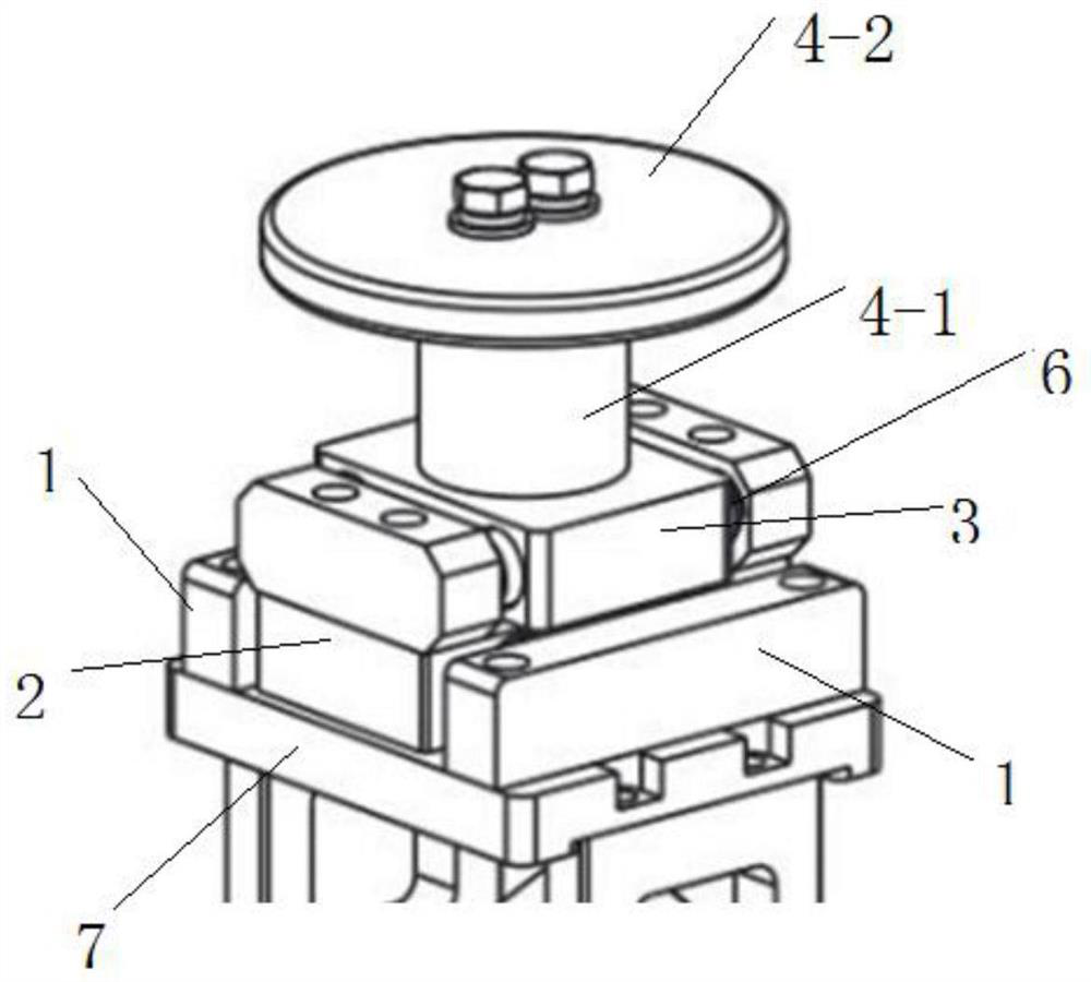
[0035] This embodiment introduces another form of manipulator flexible clamping structure on the basis of embodiment 1
[0036] like figure 2 As shown, the spring limiting block 2 and the flexible base 3 are double-layer structures, the length of the upper layer is greater than the length of the lower layer, and the first spring 5 is installed on the lower layer of the spring limiting block 2; The second spring 6 is installed on the upper layer of the spring limiting block 2 and the flexible base 3 . The above-mentioned design can effectively expand its flexible range of motion, and is suitable for situations where the fixed plate 1 is installed at a small location.
[0037] Preferably, the operation block 4 includes a cylindrical clamping part 4-1 for the manipulator to clamp and an anti-sliding disc 4-2 fixed on the top of the cylindrical clamping part 4-1.
Embodiment 3
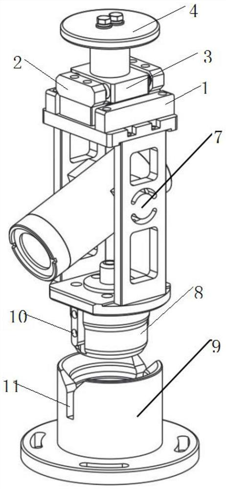
[0039] like image 3 As shown, it also includes a frame 7 for fixing the object to be clamped, and the two fixing plates 1 are fixed above the frame 7 .
[0040] It also includes a guide assembly, which includes an axial guide sleeve 8 fixedly installed on the frame 7 and an axial positioning sleeve 9 fixedly installed on the target position; the top end of the axial positioning sleeve 9 is open, and the The axial guide sleeve 8 is inserted downward into the axial positioning sleeve 9 to achieve axial positioning.
[0041] The outer wall of the axial guide sleeve 8 is provided with a circumferential positioning pin 10, and the axial positioning sleeve 9 is provided with a circumferential positioning groove 11 for the insertion of the circumferential positioning pin 10, and the circumferential positioning pin 10 is inserted into the circumferential positioning groove 11 to achieve circumferential positioning.
[0042] As a preference, both the outer diameter of the axial guid...
PUM
 Abstract
Description
Claims
Application Information
 - R&D
- Intellectual Property
- Life Sciences
- Materials
- Tech Scout
- Unparalleled Data Quality
- Higher Quality Content
- 60% Fewer Hallucinations
Browse by: Latest US Patents, China's latest patents, Technical Efficacy Thesaurus, Application Domain, Technology Topic, Popular Technical Reports.
© 2025 PatSnap. All rights reserved.Legal|Privacy policy|Modern Slavery Act Transparency Statement|Sitemap|About US| Contact US: help@patsnap.com


